On-vehicle electronic controller

Inactive Publication Date: 2002-11-14
MITSUBISHI ELECTRIC CORP
View PDF1 Cites 16 Cited by
  • Summary
  • Abstract
  • Description
  • Claims
  • Application Information

AI Technical Summary

Problems solved by technology

A conventional device configured thus is disadvantageous as follows: the LSI 2 is large in size because the CPU 3 handles quite a large number of inputs and outputs, the parallel capacitors 16 and 22 acting as noise filters require capacitors having a variety of capacities in order to obtain a desired filter constant, causing difficulty in standardization, and a large capacitor is needed to obtain a large filter constant, increasing the ECU 1 in size.
However, this method requires noise filters with a variety of capacities and is not suitable for standardization of the device.
Besides, a capacitor demands a large capacity to obtain a sufficient filter constant and is not suitable for miniaturization of the device.
In this method, although a filter constant can be changed freely, a microprocessor bears a la

Method used


Image

  • On-vehicle electronic controller
  • On-vehicle electronic controller
  • On-vehicle electronic controller

Examples


embodiments 2

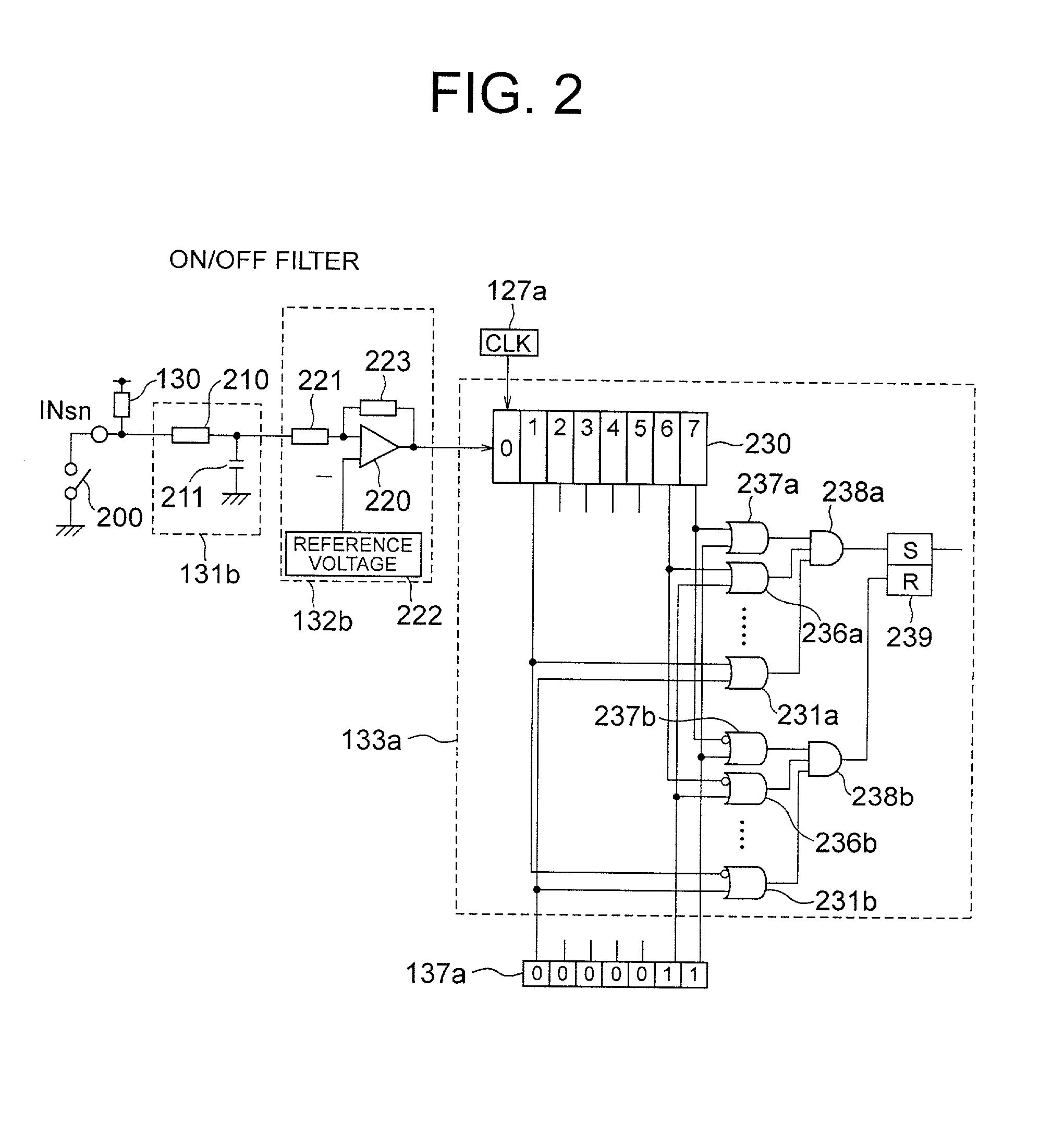
[0214] FIG. 6 shows a variable filter circuit for an ON / OFF signal according to Embodiment 2 of the present invention.

[0215] In FIG. 6, an input signal INsn having a low-resistance bleeder resistor 130 is connected to a parallel small capacitor 211 of a dozen pF or so via a series resistor 210 having a high resistance of several hundreds K.OMEGA., which is an upper limit value in practical use.

[0216] Reference numeral 131b denotes a noise filter composed of the series resistance 210 and the small capacitor 211. The noise filter absorbs and smoothes high-frequency noise.

[0217] Reference numeral 132b denotes a level-judging comparator composed of an input resistor 221, a reaction resistor 223, and a comparator 220. A predetermined reference voltage 222 (voltage Von) is applied to the inverted input of the comparator 220.

[0218] Therefore, when a charging voltage of the small capacitor 211 is at a reference voltage Von or more, the output of the comparator 220 is set at "H" (logic "1")....

embodiments 3

[0227] FIG. 7 shows a variable filter circuit for an analog signal according to Embodiment 3 of the present invention.

[0228] In FIG. 7, reference numeral 135 denotes a noise filter for an analog input signal ANm. The noise filter 135 is composed of a positive clip diode 300, a negative clip diode 301, a series resistor 302, and a parallel small capacitor 303.

[0229] When excessive noise is superposed on the analog input signal ANm, the clip diodes 300 and 301 reflux noise voltage in a positive / negative circuit of power supply and prevent a voltage more than a maximum value or less than a minimum value of an assumed analog signal from being applied to the small capacitor 303.

[0230] Moreover, when an analog sensor (not shown) connected to the ANm terminal has an equivalent internal resistance, the series resistor 302 can be omitted.

[0231] A capacitor 714 (capacity C) constituting the variable filter circuit 136b is charged from filter resistors 712a to 712d via analog gate switches 713...

embodiment 4

[0235] The embodiment of FIG. 1 does not include an analog output. A DA converter for meter indication may be installed as an indirect output when necessary.

[0236] Actually, since low-speed output points of such an analog output and ON / OFF operations are not large in number, without depending upon serial communication, the output may come directly from a latch memory 115 on the side of a microprocessor 111.

[0237] Further, for fail-safe driving, even in the case of a low-speed input signal, it is important to input minimum input information required for maintaining the rotation of an engine directly to the microprocessor 111 without depending upon serial communication.

[0238] In the embodiment of FIG. 1, the clock generator 127 is disposed in the second LSI 120. A clock signal line may be added to a serial communication line and synchronization control may be carried out by using a clock signal of the microprocessor 111. Further, the clock generators of FIGS. 2, 3, and 6 are each comp...


PUM


Abstract

To miniaturize and standardize an on-vehicle electronic controller by improving an input filter circuit in the device. Direct input interface circuits and a direct output interface circuit are connected to a data bus of a microprocessor, which has a nonvolatile memory for storing a control program and so on and a RAM memory for computing. ON/OFF signals inputted from indirect input interface circuits are transmitted to the RAM memory via a variable filter circuit, in which a filter constant is set by a constant setting register, and interactive serial communication circuits. A filter constant stored in the nonvolatile memory is stored in the constant setting register via the interactive serial communication circuits.

Description

[0001] 1. Field of the Invention[0002] The present invention relates to an on-vehicle electronic controller including a microprocessor used for controlling fuel supply of a vehicle engine, and particularly concerns an on-vehicle electronic controller which is improved in handling a number of input / output signals to miniaturize the controller and is improved to standardize the controller regarding the control on various kinds of vehicles.[0003] 2. Description of the Prior Art[0004] FIG. 8 is a typical block circuit diagram showing a conventional one of such electronic controllers, in which an ECU (engine control unit) 1 composed of a single printed board includes a large LSI (integrated circuit component) 2 as a main component. In the LSI 2, a CPU (microprocessor) 3, a nonvolatile flash memory 4, a RAM memory 5, an input data selector 6, an A / D converter 7, an output latch memory 8 and so on are connected via a data bus 30.[0005] The ECU 1 operates in response to control power suppli...

Claims


Application Information

Patent Timeline
IPC IPC(8): B60R16/02B60W10/06B60W50/00F02D41/24F02D45/00G05B15/02G05B19/042G05B19/05G05D1/00G05D3/00G06F13/10G06F13/12G06F13/38G06F19/00H03H19/00
CPCB60W10/06B60W50/00B60W50/0098G05B2219/2637F02D41/28G05B19/042G05B2219/21126B60W2050/0052
Inventor NAKAMOTO, KATSUYAKITTA, MITSUHIROGOKAN, HIROSHIHASHIMOTO, KOHJI
Owner MITSUBISHI ELECTRIC CORP
Why Eureka
Try Eureka