Heat-treating furnace with magnetic field and heat treatment method using same

Inactive Publication Date: 2002-12-05
HITACHI METALS LTD
View PDF0 Cites 21 Cited by
  • Summary
  • Abstract
  • Description
  • Claims
  • Application Information

AI Technical Summary

Benefits of technology

0010] Accordingly, an object of the present invention is to provide a small, high-safety, high-accur

Problems solved by technology

However, the magnetic field-generating means in this heat-treating furnace with a magnetic field is constituted by an electromagnet having a coil, to which as large electric current as 500-800 A should be supplied to generate a magnetic field of 1.0 T or more, unsatisfactory from the aspect of safety.
It also needs a facility for using large electric power, taking large electricity cost for generating a magnetic field, and a large amount of cooling water should be used to remove heat generated by large electric current.
Because of these requirements, it suffers from high treatment cost.
Though the consumption of exciting current can be made smaller when a superconductive coil is u

Method used


Image

  • Heat-treating furnace with magnetic field and heat treatment method using same
  • Heat-treating furnace with magnetic field and heat treatment method using same
  • Heat-treating furnace with magnetic field and heat treatment method using same

Examples


example 2

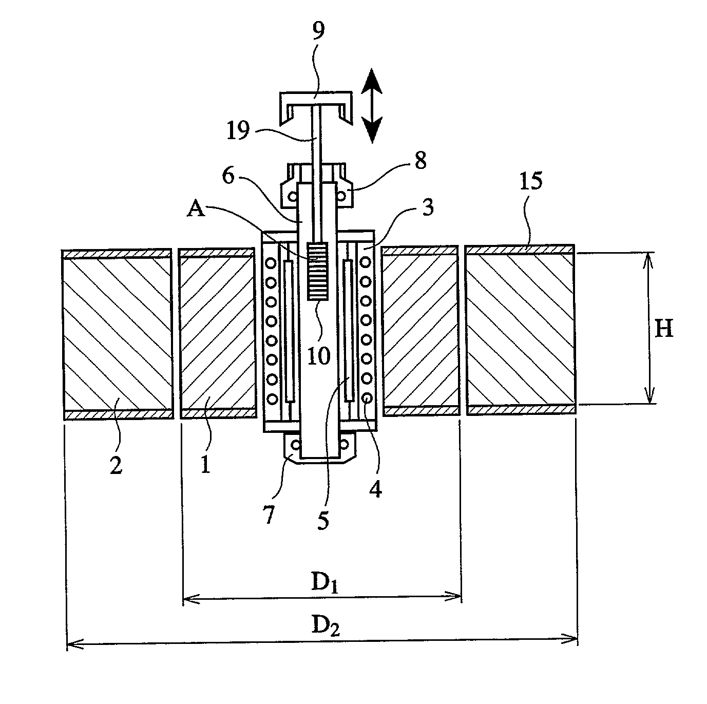
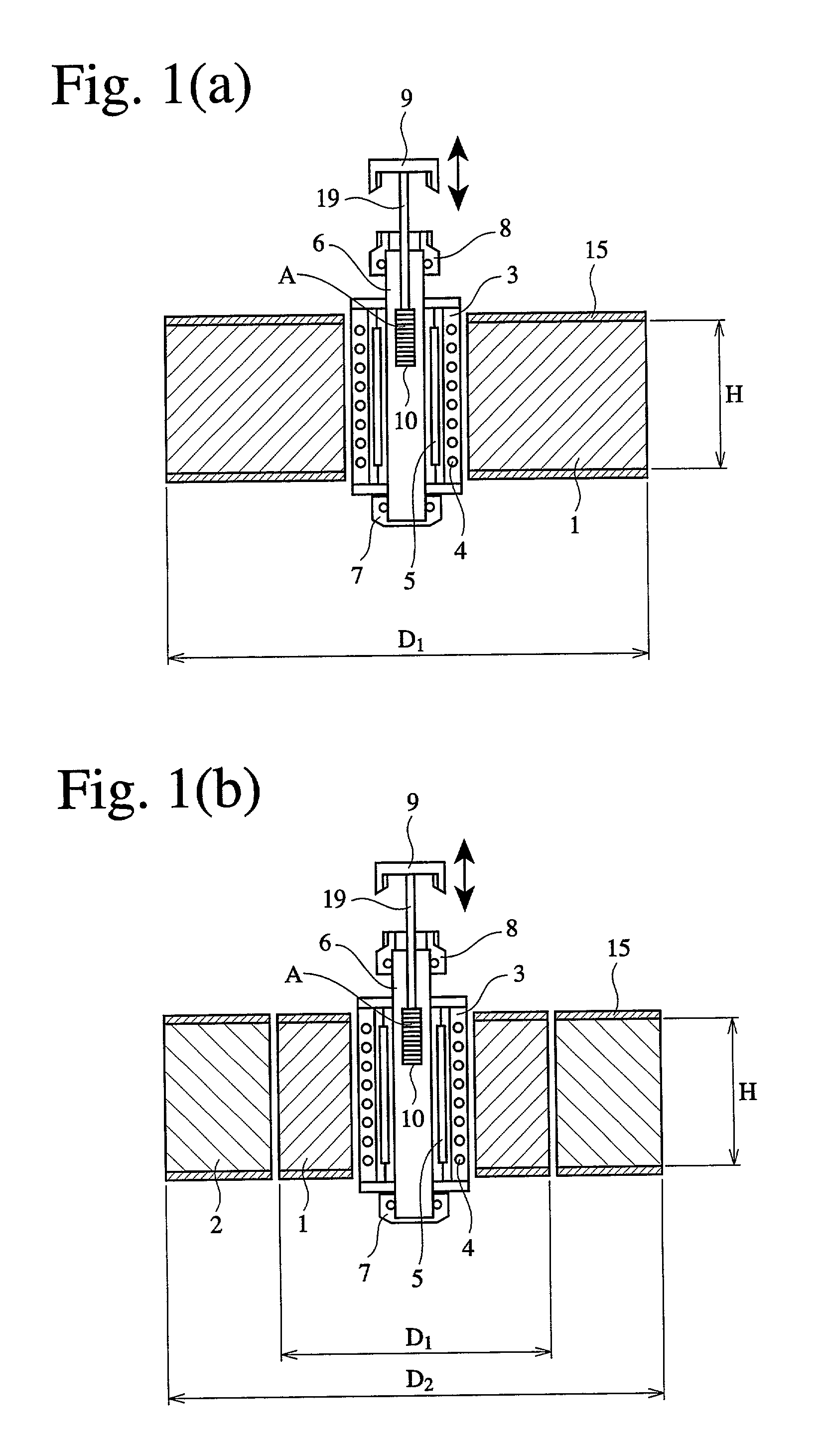
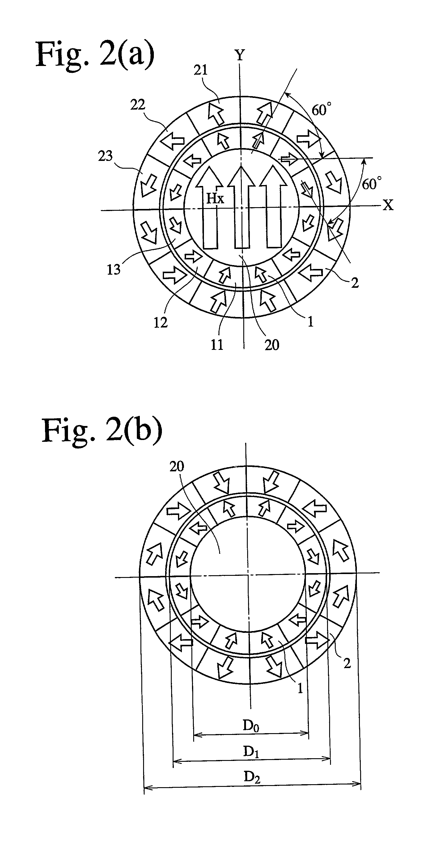
[0083] Heat treatment was carried out in a magnetic field in the same manner as in Example 1 except for changing the axial lengths of an outer, ring-shaped, permanent magnet assembly 2 and an inner, ring-shaped, permanent magnet assembly 1A as shown in FIG. 3, and preventing the wafer substrates from rotating with the inner, ring-shaped, permanent magnet assembly 1A. Each ring-shaped, permanent magnet assembly was constituted by three types of fan-shaped permanent magnet segments having different magnetization directions, which were arranged in the number of 12 in a peripheral direction. Each permanent magnet segment has the same magnetization direction as shown in FIG. 2.

[0084] As a heat-treating furnace with a magnetic field for 8-inch wafer substrates, the inner, ring-shaped, permanent magnet assembly 1A had an inner diameter D.sub.0 of 360 mm and an outer diameter D.sub.1 of 560 mm. The outer, ring-shaped, permanent magnet assembly 2A had an outer diameter D.sub.2 of 1100 mm. Th...

example 3

[0089] A heat-treating furnace with a magnetic field comprising an inner, ring-shaped, permanent magnet assembly 1 and an outer, ring-shaped, permanent magnet assembly 2 each constituted by 12 permanent magnet segments having magnetization directions shown in FIG. 2 was used as in Example 1. The inner, ring-shaped, permanent magnet assembly 1 had an inner diameter D.sub.0 of 360 mm and an outer diameter D.sub.1 of 560 mm. The outer, ring-shaped, permanent magnet assembly 2 had an outer diameter D.sub.2 of 1100 mm. Both ring-shaped, permanent magnet assemblies 1, 2 had an axial length (height) H of 420 mm.

[0090] The inner, ring-shaped, permanent magnet assembly 1 has a case 11 provided with a gear on a lower surface, so that it is rotatable relative to the outer, ring-shaped, permanent magnet assembly 2 and the wafer substrates by a motor. Accordingly, the relative position of the wafer substrates to the inner, ring-shaped, permanent magnet assembly 1 changed. This Example is the sam...

example 4

[0092] FIG. 4 shows another example of a combination of an inner, ring-shaped, permanent magnet assembly 1B and an outer, ring-shaped, permanent magnet assembly 2B. The outer, ring-shaped, permanent magnet assembly 2B is shorter in an axial length (height) than the inner, ring-shaped, permanent magnet assembly 1B. In the embodiment of FIG. 5, the outer, ring-shaped, permanent magnet assembly 2C is shorter in an axial length (height) than the inner, ring-shaped, permanent magnet assembly 1C, and the inner and outer ring-shaped, permanent magnet assemblies 1C, 2C have an axial length, which becomes gradually shorter as it goes toward outside in a radial direction. With this structure, the leaked magnetic field in an axial direction can be reduced. This can make the ring-shaped, permanent magnet assemblies smaller and lighter in weight, resulting in a shorter heat-treating furnace with a magnetic field.

[0093] FIG. 6(a) shows an installation example, in which an outer, ring-shaped, perm...


PUM

PropertyMeasurementUnit
Diameteraaaaaaaaaa
Diameteraaaaaaaaaa
Diameteraaaaaaaaaa

Abstract

A heat-treating furnace with a magnetic field comprising (a) a magnetic field-generating means constituted by an outer, ring-shaped, permanent magnet assembly comprising a plurality of permanent magnet segments combined with their magnetization directions oriented such that a magnetic flux flows in a diameter direction, and an inner, ring-shaped, permanent magnet assembly disposed inside the outer, ring-shaped, permanent magnet assembly and comprising a plurality of permanent magnet segments combined with their magnetization directions oriented such that a magnetic flux flows in a diameter direction; and (b) a heat treatment means disposed in a center hole of the inner, ring-shaped, permanent magnet assembly and comprising a cooling means, a heating means, and a heat-treating container containing heat-treating holder for holding a plurality of articles to be heat-treated in this order from outside, wherein an axial center of a magnetic field generated by the inner and outer ring-shaped, permanent magnet assemblies is substantially identical with an axial center of an article assembly in the heat-treating container.

Description

[0001] The present invention relates to a furnace for heat-treating wafer substrates for forming MR (magnetoresistive) heads, GMR (giant magnetoresistive) heads, MRAM (magnetic random access memory), etc. in a magnetic field in their production processes, and a heat treatment method using such a furnace.PRIOR ART[0002] A magnetic head generally has a structure in which a plurality of ferromagnetic layers are laminated on a substrate. For instance, the GMR head has a structure comprising non-magnetic insulating layers between ferromagnetic layers. The MRAM head has a structure comprising antiferro magnetic layers, a pinned magnetic layer, a non-magnetic conductive layer and free magnetic layers in this order from the side of a substrate. The pinned magnetic layers are entirely magnetized in one direction.[0003] To magnetize the pinned layer in one direction, it is necessary to heat-treat or anneal a substrate provided with thin magnetic layers in a magnetic field. An oriented magneti...

Claims


Application Information

Patent Timeline
IPC IPC(8): H01L21/68C21D1/04H05B6/22
CPCH05B6/22C21D1/04Y02P10/25H01L21/68
Inventor KURIYAMA, YOSHIHIKOUSHIJIMA, MAKOTOAZUMA, YASUYUKI
Owner HITACHI METALS LTD
Why Eureka
Try Eureka