

Ceramic honeycomb structure
a honeycomb and honeycomb technology, applied in the direction of physical/chemical process catalysts, other chemical processes, separation processes, etc., can solve the problems of unbalanced raw material flow in the outer wall and in the ribs, and achieve the effects of increasing isostatic strength, reducing thermal shock resistance, and increasing pressure loss
- Summary
- Abstract
- Description
- Claims
- Application Information
AI Technical Summary
Benefits of technology
Problems solved by technology
Method used
Image


Examples
Embodiment Construction
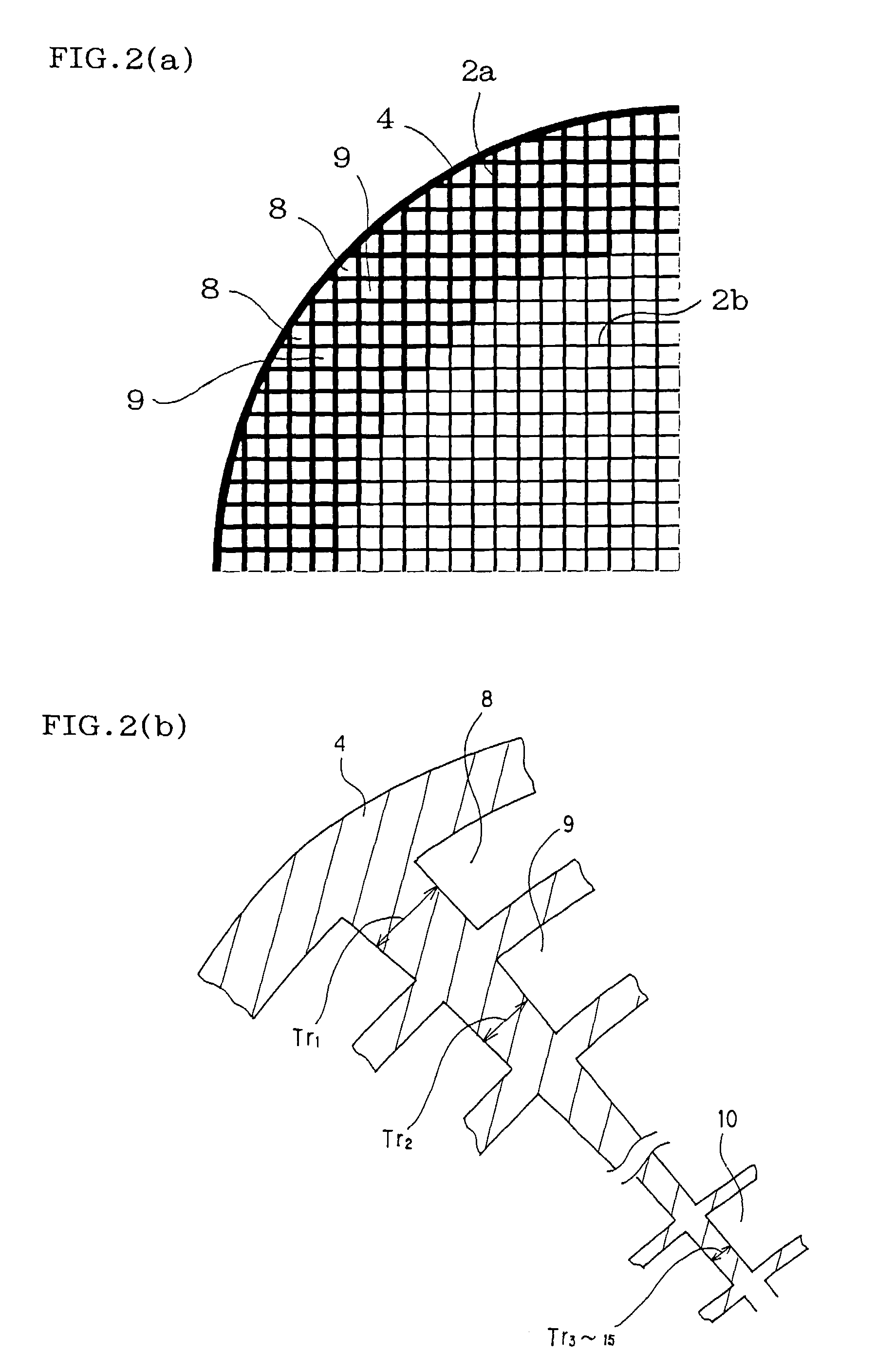
is a case where the wall thickness of the outermost peripheral cell (starting cell) to the 15th cell was set at 0.150 mm and each wall of the 16th to 20th cells was formed as follows:
[0120] the section of said each wall had such an inverse trapezoidal shape as the minor base of inverse trapezoid was present inwardly, the minor base of inverse trapezoid was shorter as said each wall was more inward, and the thickness of the cell wall having the shortest minor base was identical to the basic cell wall thickness (Tc) (0.075 mm). Example 19 is a case where the wall thickness of the outermost peripheral cell (starting cell) to the 15th cell was set at 0.150 mm and each wall of the 16th to 20th cells was formed as follows:
[0121] the section of said each wall had such a spool shape as the inner side of spool was shorter than the outer side, the inner side of spool was shorter as said each wall was more inward, and the thickness of the cell wall having the shortest inner side was identical ...
PUM
| Property | Measurement | Unit |
|---|---|---|
| diameter | aaaaa | aaaaa |
| diameter | aaaaa | aaaaa |
| thickness | aaaaa | aaaaa |
Abstract
Description
Claims
Application Information