
Ceramic heater

a ceramic heater and ceramic plate technology, applied in the field of ceramic plates, can solve the problems of thermal shock applied to the ceramic plate, the .delta.t of the ceramic plate may decrease to approximately 150.degree. c, and the prior art may suffer, so as to achieve good repeatability and increase the amount of positional offset

Inactive Publication Date: 2003-01-23
IBIDEN CO LTD
View PDF4 Cites 64 Cited by
  • Summary
  • Abstract
  • Description
  • Claims
  • Application Information

AI Technical Summary

Benefits of technology

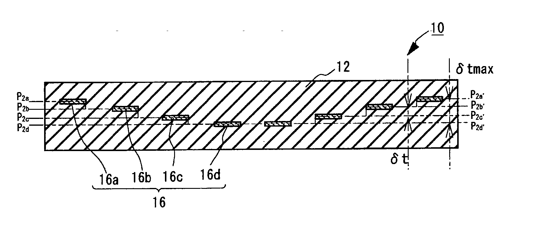
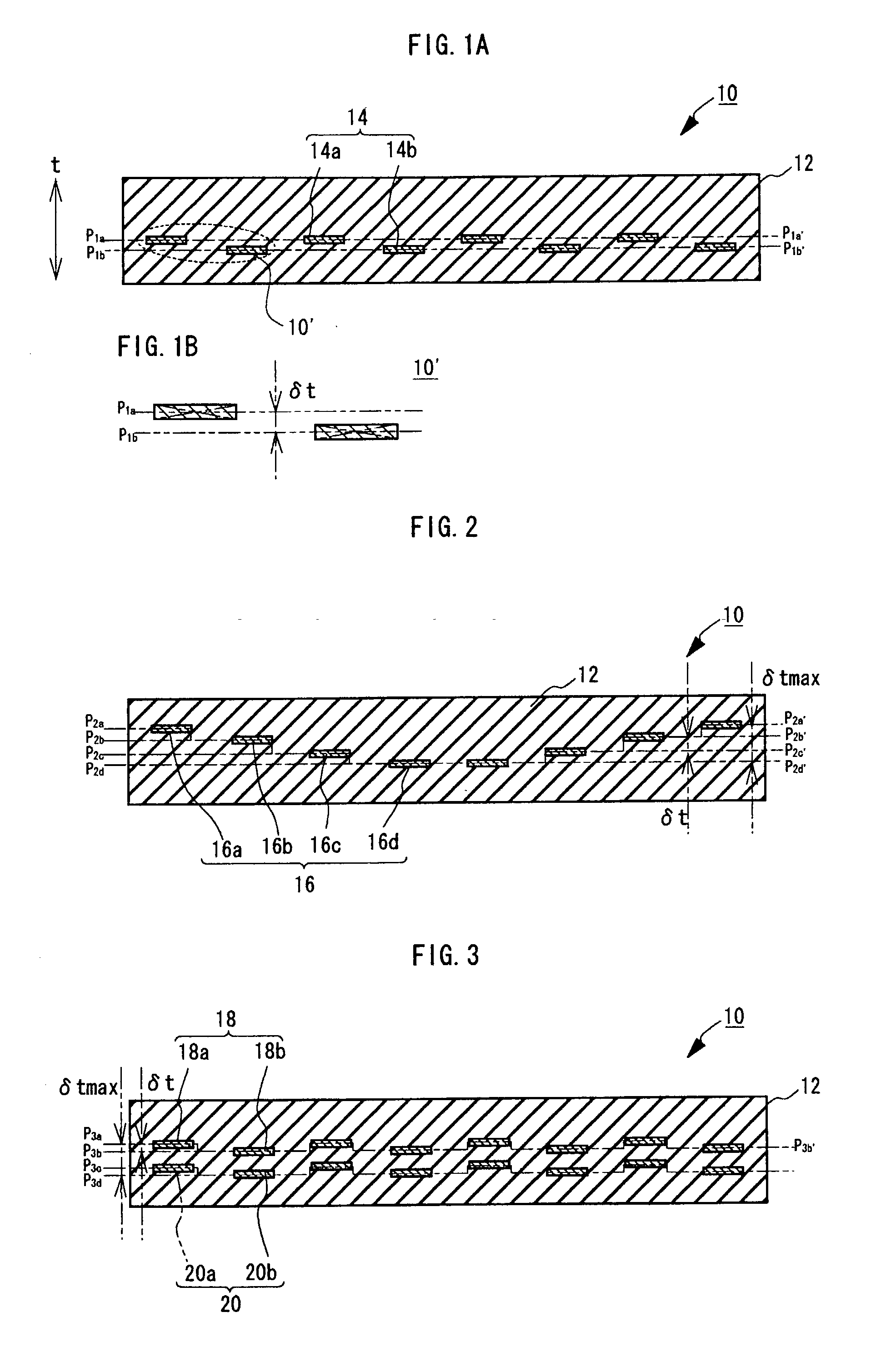
[0012] The fact based on the fundamental experiments conducted by the authors also revealed that the anti thermal shock property of the ceramic heater is better if the position of each heat generation body is varied than if the distance between heat generation bodies in the direction of thickness within the ceramic substrate is even. The inventors of the present invention has proposed, on the basis of these findings, a structure with the positional arrangement of heat generation bodies being varied in the direction of thickness of the ceramic substrate, to achieve this novel invention.
[0080] The method of production as have been described above allows laminated green sheets to be bonded with the paste layers interposed, so that the green sheet with the heat generation bodies selectively offset by the thickness of a paste layer in the direction of thickness may be readily produced. In accordance with the preferred embodiment as described above, a ceramic substrate may be produced in which the amount of positional offset of the heat generation bodies in the direction of thickness may be variably set, without significantly changing the conventional production process, at lower cost.

Problems solved by technology

Thus the Prior Art may suffer from the problem of thermal shock applied to the ceramic substrate by the expansion or shrinkage of the heater core at the time of heat-up or cool-down, due to the difference of thermal expansion rate at the sites of discontinuity.
When the heat generation bodies are embedded in the ceramic substrate there is a problem arising that the .DELTA.T of the ceramic substrate may decrease to approximately 150.degree. C. due to the thermal shock.

Method used


Image

  • Ceramic heater
  • Ceramic heater
  • Ceramic heater

Examples


example 1

[0090] (1) A ceramic paste composition (viscosity 100 Pa.multidot.s) was made by mixing 100 parts by weight of powdered aluminum nitride (available from Tokuyama Corp., mean particle diameter 1.1 .mu.m), 4 parts by weight of yttrium (mean particle diameter 0.4 .mu.m), 11.5 parts by weight of acrylic binder, 0.5 part by weight of dispersant, and 53 parts by weight of alcohol mixture containing 1-butanol and ethanol. By means of doctor blade method, sheet formation was made from the paste on a base film comprised of PET and the like to obtain a green sheet of thickness of 0.47 mm. Some openings for making through holes were punched out at predetermined positions on the green sheet.

[0091] (2) A conductive paste composition A was prepared by mixing 100 parts by weight of tungsten carbide having mean particle diameter of 1 .mu.m, 3.0 parts by weight of acrylic binder, 3.5 parts by weight of .alpha.-terpineol solvent, and 0.3 part by weight of dispersant.

[0092] Also, a conductive paste B ...

example 2

[0098] (1) A ceramic paste composition (viscosity 100 Pa.multidot.s) was made by mixing 100 parts by weight of powdered aluminum nitride (available from Tokuyama Corp., mean particle diameter 1.1 .mu.m), 4 parts by weight of yttrium (mean particle diameter 0.4 .mu.m), 11.5 parts by weight of acrylic binder, 0.5 part by weight of dispersant, and 53 parts by weight of alcohol mixture containing 1-butanol and ethanol. By means of doctor blade method, sheet formation was made from the paste on a base film comprised of PET and the like to obtain a green sheet of thickness of 0.47 mm. Some openings for making through holes were punched out at predetermined positions on the green sheet.

[0099] (2) A conductive paste composition A was prepared by mixing 100 parts by weight of tungsten carbide having mean particle diameter of 1 .mu.m, 3.0 parts by weight of acrylic binder, 3.5 parts by weight of .alpha.-terpineol solvent, and 0.3 parts by weight of dispersant.

[0100] Also, a conductive paste B...

example 3

[0103] (1) 100 parts by weight of powdered aluminum nitride (available from Tokuyama Corp., mean particle diameter 1.1 .mu.m), 4 parts by weight of yttrium (mean particle diameter 0.4 .mu.m ), 11.5 parts by weight of acrylic binder were housed in a mold to pressurize at 14.7 MPa.multidot.s (150 kg / cm.sup.2) to obtain a green body of thickness 7 mm.

[0104] (2) The surface of green body was spot faced by means of a bit of diameter 2.5 mm to form spiral groove. One green body was spot faced in depths of 0.5 mm and 1.7 mm for every two rounds, another was spot faced in depths of 0.5 mm and 0.75 mm for every two rounds, so that the cross-section became a hatch.

[0105] (3) A tungsten wire was wound spirally. heat generation body having cross-section of 2.5 mm by 0.5 mm was disposed along with the groove. A mixture of 100 parts by weight of powdered aluminum nitride (available from Tokuyama Corp., mean particle diameter 1.1 .mu.m), 4 parts by weight of yttrium (mean particle diameter 0.4 .mu...


PUM

PropertyMeasurementUnit
temperatureaaaaaaaaaa
thicknessaaaaaaaaaa

Abstract

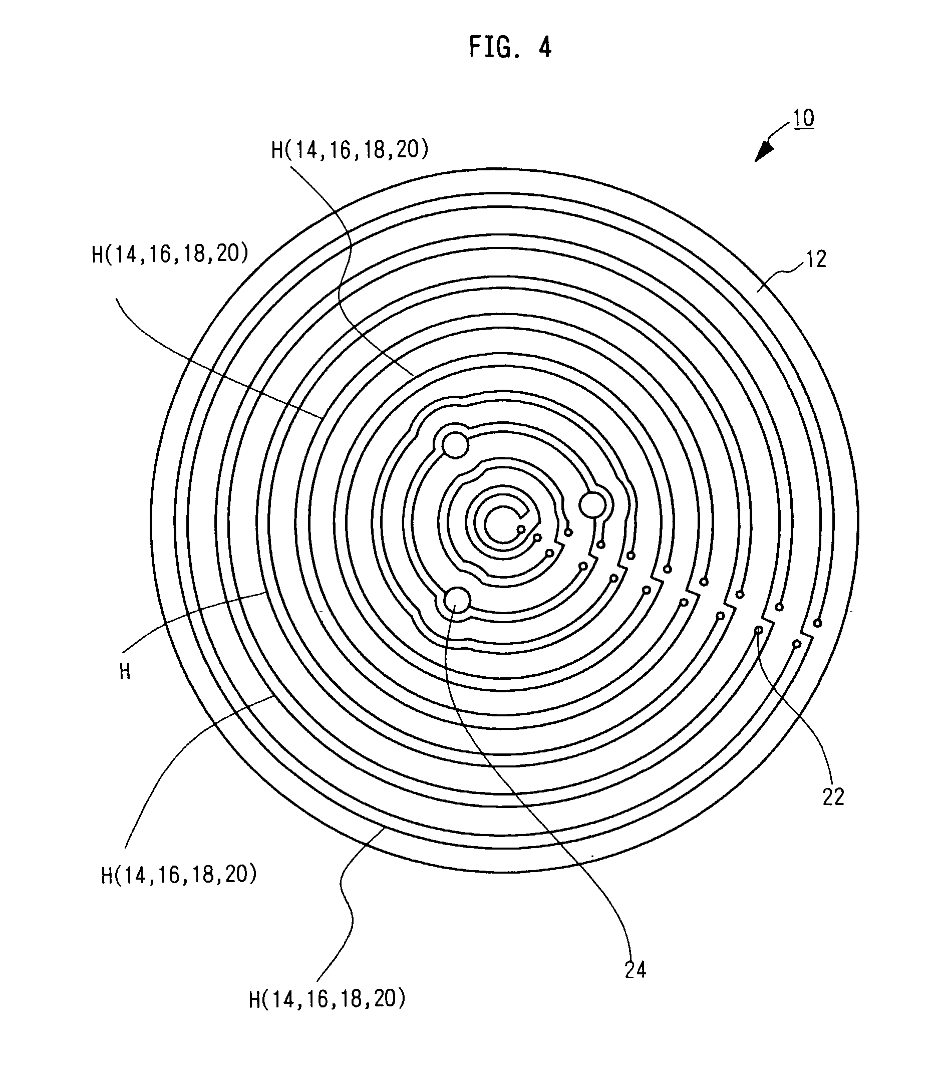
The present invention provides a ceramic heater having better anti thermal shock property. A ceramic substrate 12 is formed by providing heat generation bodies 14a and 14b on the surface of a green sheet made from a slurry containing powdered ceramics, sandwiching the green sheet with other green sheets from both upper and lower sides and then laminating and pressing the compiled green sheets. At least some of the heat generation bodies 14a and 14b are disposed on a level P1b offset from a level P1a of other heat generation bodies in the direction of thickness of the ceramic substrate 12.

Description

[0001] The present invention relates to a ceramic heater, and more particularly to a ceramic heater for use in production and inspection processes of semiconductors.[0002] Applied semiconductor products are indispensable in many industrial fields. As a typical example, semiconductor chips are produced by slicing a silicon monocrystalline to a predetermined thickness to produce a silicon wafer, on which are formed a variety of circuits.[0003] In the production process of such variety of circuits, high frequency spattering technique or plasma etching technique may be used for heating the silicon wafer in order to form components such as conductive thin films thereon. In order to successfully achieve the high frequency spattering or plasma etching, ceramic heaters have been become popular in recent years, which is made of sintered ceramic materials.[0004] As a type of ceramic heater, one incorporating a resistive heat-generation body (referred to as a heat generation body herein below)...

Claims


Application Information

Patent Timeline
Patent Type & Authority Applications(United States)
IPC IPC(8): H05B3/14H05B3/28
CPCH05B3/143H05B3/283
Inventor ITO, YASUTAKA
Owner IBIDEN CO LTD
Learn More