Shielded strip line device and method of manufacture thereof

a technology of shielding strip and strip line, which is applied in the direction of waveguide devices, electrolytic capacitors, waveguide types, etc., can solve the problems of lowering signal quality, increasing the impedance of capacitors, and placing more difficult demands on noise filter bypass devices and power decoupling devices

Inactive Publication Date: 2003-03-20
NEC CORP
View PDF0 Cites 22 Cited by
  • Summary
  • Abstract
  • Description
  • Claims
  • Application Information

AI Technical Summary

Problems solved by technology

However, this causes an increase in the high frequency current that flows through the circuit, in particular the power supply circuit, causing significant increase in electromagnetic radiation and lowering of signal quality and thus placing more difficult demands on the performance of noise filter bypass devices and power decoupling devices.
However, even these capacitors increase dramatically in impedance and cannot meet recent demands as filter bypass devices and power decoupling devices in high frequency ranges

Method used


Image

  • Shielded strip line device and method of manufacture thereof
  • Shielded strip line device and method of manufacture thereof
  • Shielded strip line device and method of manufacture thereof

Examples


first embodiment

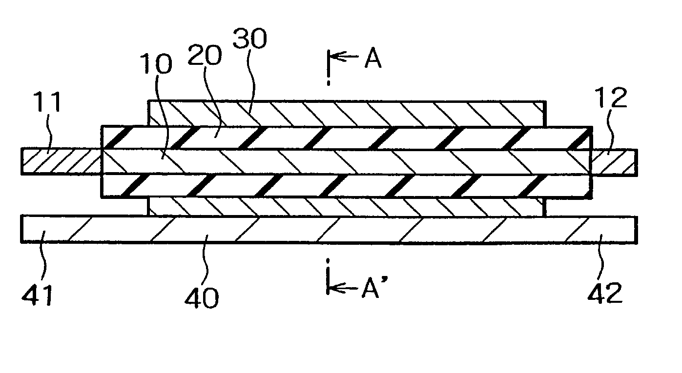
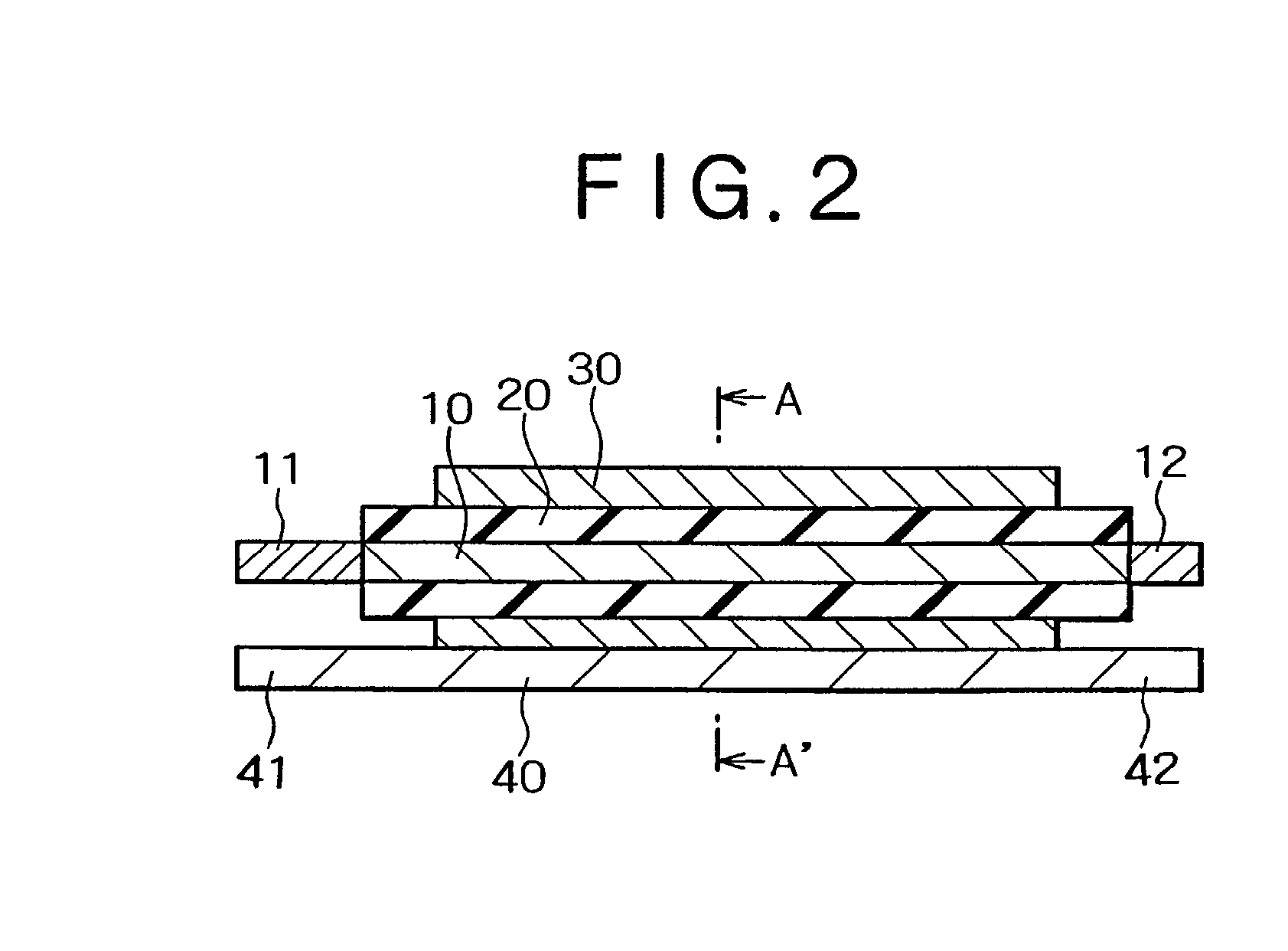
[0029] Embodiments of the present invention shall now be described with reference to the attached drawings. First, the present invention shall be described. FIG. 2 is a sectional view, showing a shielded strip line device of the embodiment, and FIG. 3 is a sectional view, showing the section along line A-A' of FIG. 2.

[0030] As shown in FIGS. 2 and 3, with the shielded strip line device of the present embodiment, a metal plate 10, which comprises a valve metal and is substantially of a planar shape, is provided. Valve metal plate 10 is formed, for example, of aluminum. Valve metal plate 10 is rectangular in shape and, for example, 110 .mu.m in thickness, 20 mm in length, and 10 mm in width. The surface of valve metal plate 10, that is, the top face, rear face, and end faces are increased by approximately 200 times in surface area by electrolytic etching in an electrolytic solution.

[0031] A dielectric oxide film 20 is formed on the surface of this valve metal plate 10. Dielectric oxid...

sixth embodiment

[0072] this invention shall now be described. FIG. 4 is a perspective view, showing the shielded strip line device of this embodiment. As shown in FIG. 4, the shielded strip line device of this embodiment is provided with a formed body 13, comprising a sintered compact of tantalum powder with an average particle diameter, for example, of 0.5 .mu.m. Formed body 13 has the shape of a rectangular parallelepiped and, for example, is 3 mm in width, 3 mm in length, and 1.8 mm in thickness. Tantalum wires 14 and 15 are connected to the respective ends of formed body 13. Tantalum wires 14 and 15 are, for example, 0.3 mm in diameter. A metal member 16 is formed of formed body 13 and tantalum wires 14 and 15.

[0073] A dielectric oxide film (not shown) is formed on the surface of formed body 13, and on the surface of this dielectric oxide film, a conductive polymer layer, conductive carbon paste layer, and silver paste layer are formed, in the order starting from the inner side, so as to surrou...

seventh embodiment

[0082] this invention shall now be described. FIG. 5 is a perspective view, showing the shielded strip line device of this embodiment. As shown in FIG. 5, the shielded strip line device of this embodiment is provided with a cylindrical metal member 17, formed of aluminum and having a diameter of 5 mm and a length of 100 mm. The respective end parts of cylindrical metal member 17 are arranged as anode lead terminals 11a and 12a. Screw holes 11b and 12b are formed in anode lead terminals 11a and 12a, respectively.

[0083] A dielectric oxide film 21 is formed on the surface of cylindrical metal member 17, and on the outer side of dielectric oxide film 21, a conductive polymer layer, comprising polyaniline having para-toluenesulfonic acid as a dopant, a conductive carbon paste layer, and a silver paste layer are formed in that order starting from the inner side. A conductor layer 36 is formed of this conductive polymer layer, conductive carbon paste layer, and silver past layer. A metal p...


PUM


Abstract

A dielectric oxide film is formed on the surface of a valve metal plate formed of aluminum and a conductive polymer layer is provided so as to cover the valve metal plate and the dielectric oxide film. The conductive polymer layer is formed of polyaniline having para-toluenesulfonic acid as a dopant. A conductive carbon paste layer and a silver paste layer are provided at the outer side of the conductive polymer layer and a metal plate, comprising a copper foil, is overlapped onto the silver paste layer. Anode lead terminals are connected to the ends of the valve metal plate and the respective end parts of the metal plate are arranged as cathode lead terminals. A shield strip line device, which is low in impedance, especially in high-frequency ranges of 100 MHz or more, and is favorably adapted to high speed and high frequencies, mainly for use as a bypass device for a noise filter or as a decoupling device, is thus obtained.

Description

[0001] 1. Technical Field of the Invention[0002] This invention relates to a shielded strip line device to be mounted on a circuit board or an electronic substrate and a method of manufacture thereof, and particularly relates to a shielded strip line device, which is favorably adapted to high speeds and high frequencies, mainly for use as a noise filter bypass device or power decoupling device, and a method of manufacturing such a shielded strip line device.[0003] 2. Description of the Related Art[0004] With the progress of scientific technologies, the making of electronic equipment more compact and higher in performance is being demanded. This is achieved, for example in switching power supplies and digital signal processing circuit parts, by making the clock frequency higher. However, this causes an increase in the high frequency current that flows through the circuit, in particular the power supply circuit, causing significant increase in electromagnetic radiation and lowering of...

Claims


Application Information

Patent Timeline
IPC IPC(8): H01G9/012H01G9/042H01G9/10H01G9/15H01P3/08H01P11/00H03H1/00
CPCH01G9/012H01G9/042H01G9/10H01G9/15Y10T29/417H01P11/003H03H1/0007H03H2001/0014H01P3/088
Inventor MASUDA, KOICHIROTOHYA, HIROKAZUSATOH, MASAHARU
Owner NEC CORP
Why Eureka
Try Eureka