Optical clock signal distribution system in WDM network

a technology of optical clock signal and optical clock, applied in the direction of optical elements, multiplex communication, instruments, etc., can solve the problems of deteriorating reference clock quality, noise generation as well as noise pass bandwidth, noise source discrimination and measures therefor,

Inactive Publication Date: 2003-03-27
FUJITSU LTD
View PDF4 Cites 12 Cited by
  • Summary
  • Abstract
  • Description
  • Claims
  • Application Information

AI Technical Summary

Problems solved by technology

Here, as a property of such networks, as the number of SDH transmission units for repeating the reference clock from clock source 100 increases, the number of PLL circuits transferring the clock also increases, which results in deterioration in the reference clock quality.
Also, PLL circuits to be provided in each SDH transmission unit have different way of implementation depending on manufacturers thereof, producing various noise generation as well as noise pass bandwidth.
Therefore, in an actual network, noise source discrimination and measures therefor become difficult, which produces a serious problem.
(1) Accumulated noise (jitter/wander) is produced as a result of increased clock repeating by PLL circuits.
(2) There is different performance between clock regeneration circuits (PLL circuits etc.) produced by different manufacturers.
(3) Synchronization configurations become complicated due to complication in topological layout of transmission units configuring a network (such as a mesh configuration).
(4) Widespread use of measurement instruments for measuring noise as well as use of SSU units for supervising noise during operation i

Method used


Image

  • Optical clock signal distribution system in WDM network
  • Optical clock signal distribution system in WDM network
  • Optical clock signal distribution system in WDM network

Examples


Embodiment Construction

[0055] The preferred embodiments of the present invention are described hereafter referring to the charts and drawings, wherein like numerals or symbols refer to like parts.

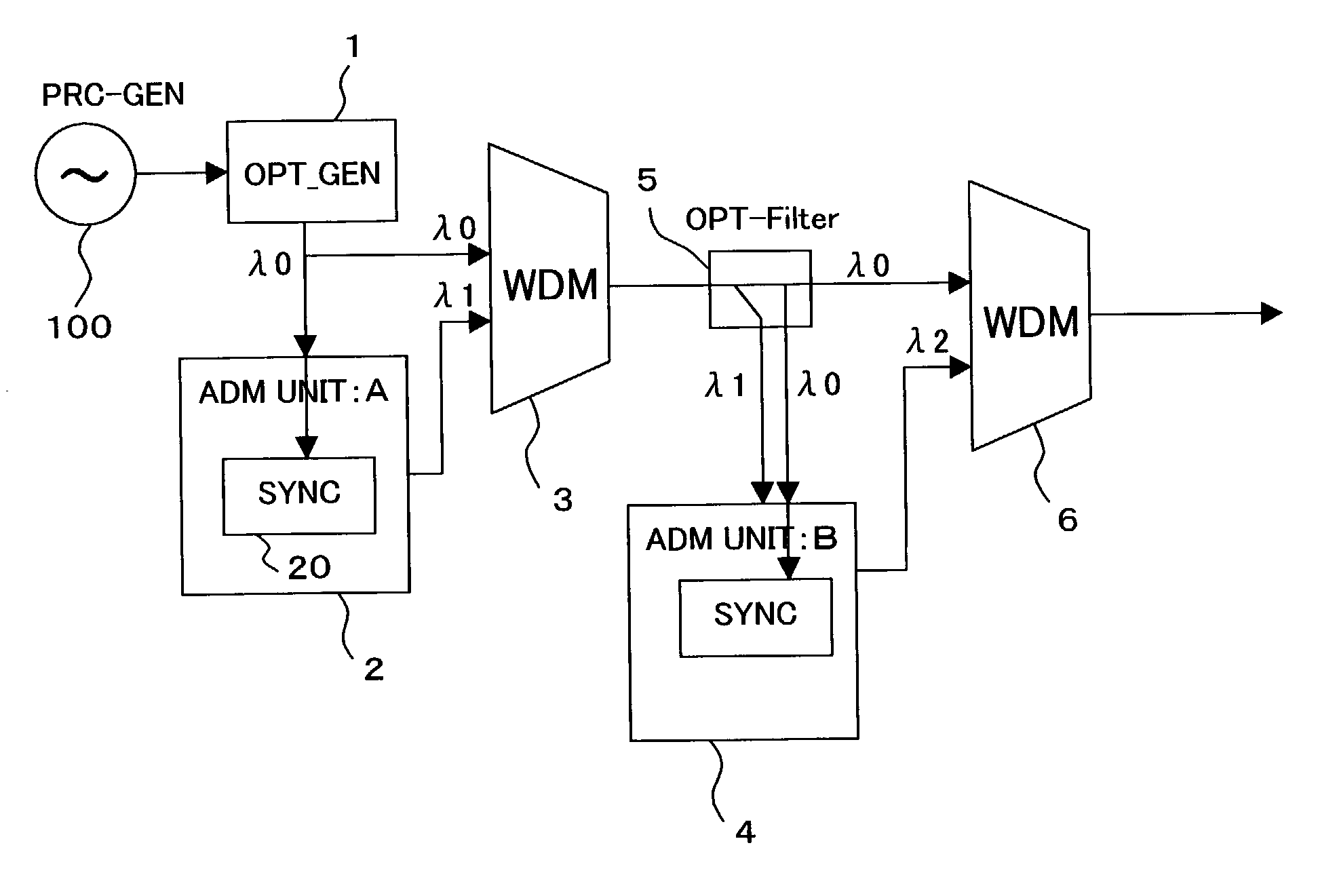
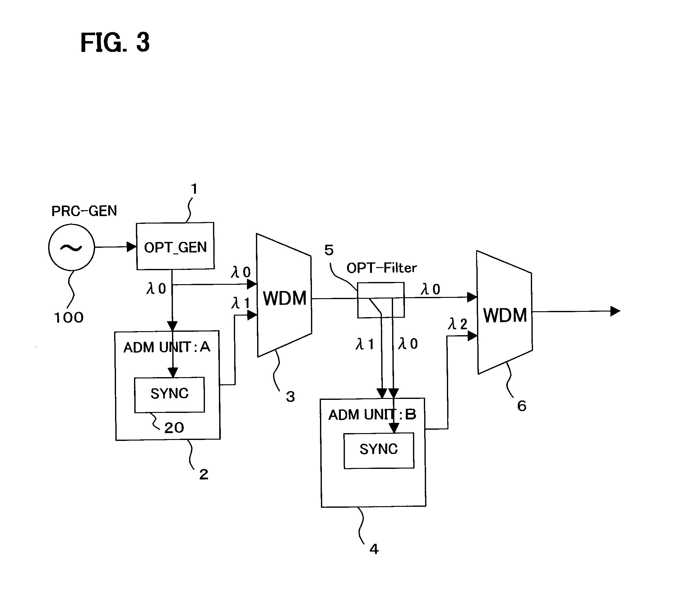
[0056] FIG. 3 shows a conceptual configuration diagram of a transmission system according to the present invention. In this system, a PRC-level clock being output from a clock source 100 is transmitted from ADM (Add Drop Multiplexing) units 2, 4 in an optical signal form without providing a clock regenerative repeating function, so that the network is operated in synchronization with one reference clock.

[0057] Clock source (PRC-GEN) 100 of PRC-level accuracy functioning as a network reference clock is constituted by, for example, a cesium atomic oscillator.

[0058] The reference clock is converted into an optical clock signal by means of an optical clock signal generator (OPT-GEN) 1. A wavelength converted into an optical clock signal is defined as .lambda.0. ADM unit 2 receives the optical clock signal having wave...


PUM


Abstract

Proposed is an optical clock distribution system in the WDM network, which particularly relates to a system to control clock synchronization between optical transmission devices constituting an optical communication network. The optical clock distribution system includes an optical clock generator converting a clock signal of PRC (Primary Reference Clock) level into an optical clock signal having a wavelength lambd0; a wavelength multiplexer wavelength-multiplexing the optical clock signal having wavelength lambd0 together with other optical wavelength data; and a wavelength-demultiplexer provided in a unit of the network, wavelength-demultiplexing the optical clock signal having wavelength lambd0, wherein the other optical wavelength data are processed in the unit of the network using the wavelength-demultiplexed optical clock signal having wavelength lambd0 as a reference clock.

Description

[0001] 1. Field of the Invention[0002] The present invention relates to an optical clock distribution system in a wavelength division multiplexing (WDM) network and more particularly a system for controlling clock synchronization between optical transmission units constituting an optical communication network.[0003] 2. Prior Arts[0004] Currently, voice and data are transmitted in various forms such as STM (Synchronous Transfer Mode), ATM (Asynchronous Transfer Mode) and IP (Internet Protocol) through an optical communication network, in which an SDH (Synchronous Digital Hierarchy) / SONET (Synchronous Optical Network) system is employed as a backbone system.[0005] Meanwhile, as a result of ongoing explosive increase of the Internet line demand in recent years, higher bit rate (ranging from 2.5 Gbps to 10 Gbps or 40 Gbps) of TDM (Time Division Multiplexing) has been introduced in each transmission unit, and at the same time efficient utilization of transmission capacity in an optical f...

Claims


Application Information

Patent Timeline
IPC IPC(8): H04B10/032H04B10/2507H04B10/03H04B10/275H04B10/556H04J3/06H04J14/02H04L7/00
CPCH04J3/0638H04J3/0641H04J14/0226H04J14/028H04J14/0282H04J14/0283H04J14/0284H04L7/0008H04J14/0246H04J14/025
Inventor RIKITAKE, NOBUHIROMORITA, HIROTAKATAKEGUCHI, KOJIMORIYA, RYUICHIMATSUI, HIDEKI
Owner FUJITSU LTD
Why Eureka
Try Eureka