Vehicle-mounted four-cycle engine control device

a control device and four-cycle technology, applied in electrical control, pedestrian/occupant safety arrangement, tractors, etc., can solve problems such as engine parts scorching, bearing wear abnormal, engine durability reduction,

Inactive Publication Date: 2003-04-03
SUZUKI MOTOR CORP
View PDF13 Cites 20 Cited by
  • Summary
  • Abstract
  • Description
  • Claims
  • Application Information

AI Technical Summary

Problems solved by technology

However, in cases where the user continues to travel having failed to notice lighting of the oil pressure warning lamp 3, problems are readily produced such as abnormal wear of bearings, e.g., such as those used for the piston rings, crankshaft, camshaft and so forth, reduced engine durability, and scorching of engine parts.
Furthermore, with a conventional structure in which the above-mentioned oil pressure switch 2 alone is provided, there is the drawback that when an apparent drop in lubricating oil pressure is attributable to failure of the above-mentioned oil pressure sensor, the engine is then stopped urgently even if a lubricating oil pressure drop has not actually occurred.

Method used


Image

  • Vehicle-mounted four-cycle engine control device
  • Vehicle-mounted four-cycle engine control device
  • Vehicle-mounted four-cycle engine control device

Examples


first embodiment

[0061] A description will be provided next of a control device of the engine B. FIG. 3 is a circuit diagram of the control device C1 according to the

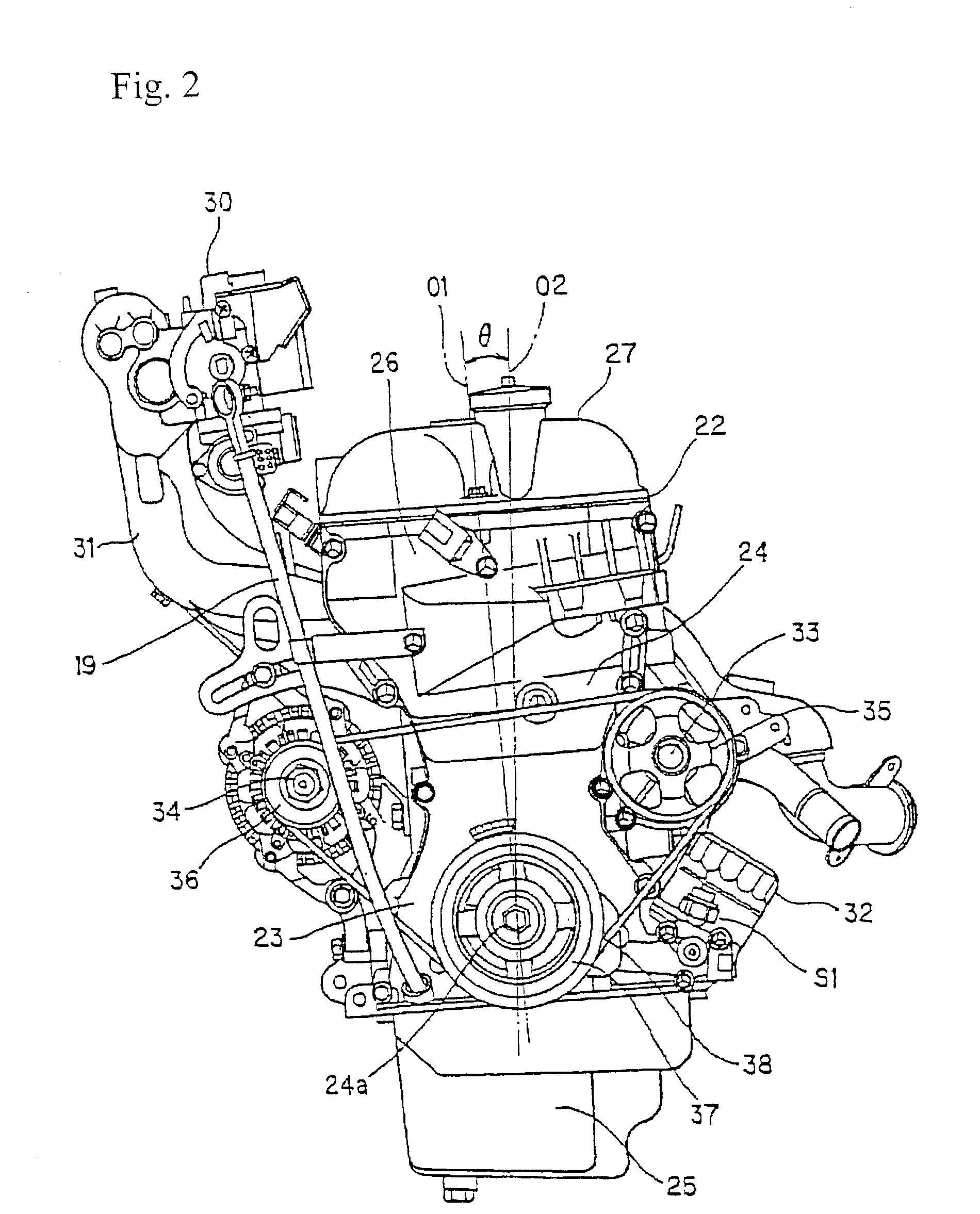
[0062] This control device C1 includes an oil pressure switch S1 which is an oil pressure detecting sensor and is provided at the front of the crankcase 23 as described hereinabove. An oil pressure warning lamp 39 constitutes one example of a warning instrument. An ECU (Engine Control Unit) 40 is also utilized. The control device C1 is connected to an ignition switch 41.

[0063] When the pressure of lubricating oil which is being circulated under pressure inside the engine body 22 is lower than a predetermined reference pressure, the oil pressure switch S1 is turned ON by a diaphragm (not shown) which is connected to the oil pressure switch S1, and is turned OFF by the diaphragm when this pressure is approximately equal to or above the predetermined reference pressure. When ON, an ON signal (low pressure signal) is output and, when OFF, a...

second embodiment

[0098] This control device C3 includes a rollover detecting sensor S2', which is disposed in the center section of the above-described vehicle body 5, and an ECU (Engine Control Unit) 42'. With the exception of differences in the constitution of the rollover detecting sensor S2', the constitution is the same as that for the control device C2 described above. Thus, the rollover detecting sensor S2' alone is described here, a description of other constituent elements which are the same having been omitted, which elements have been assigned the same reference numerals to which "'" has been added.

[0099] A Hall IC 43 has been employed for the rollover detecting sensor S2' which is constituted so as to output a rollover signal when inclination of the above-described vehicle body 5 is greater than a preset angle, e.g., approximately 60 degrees.

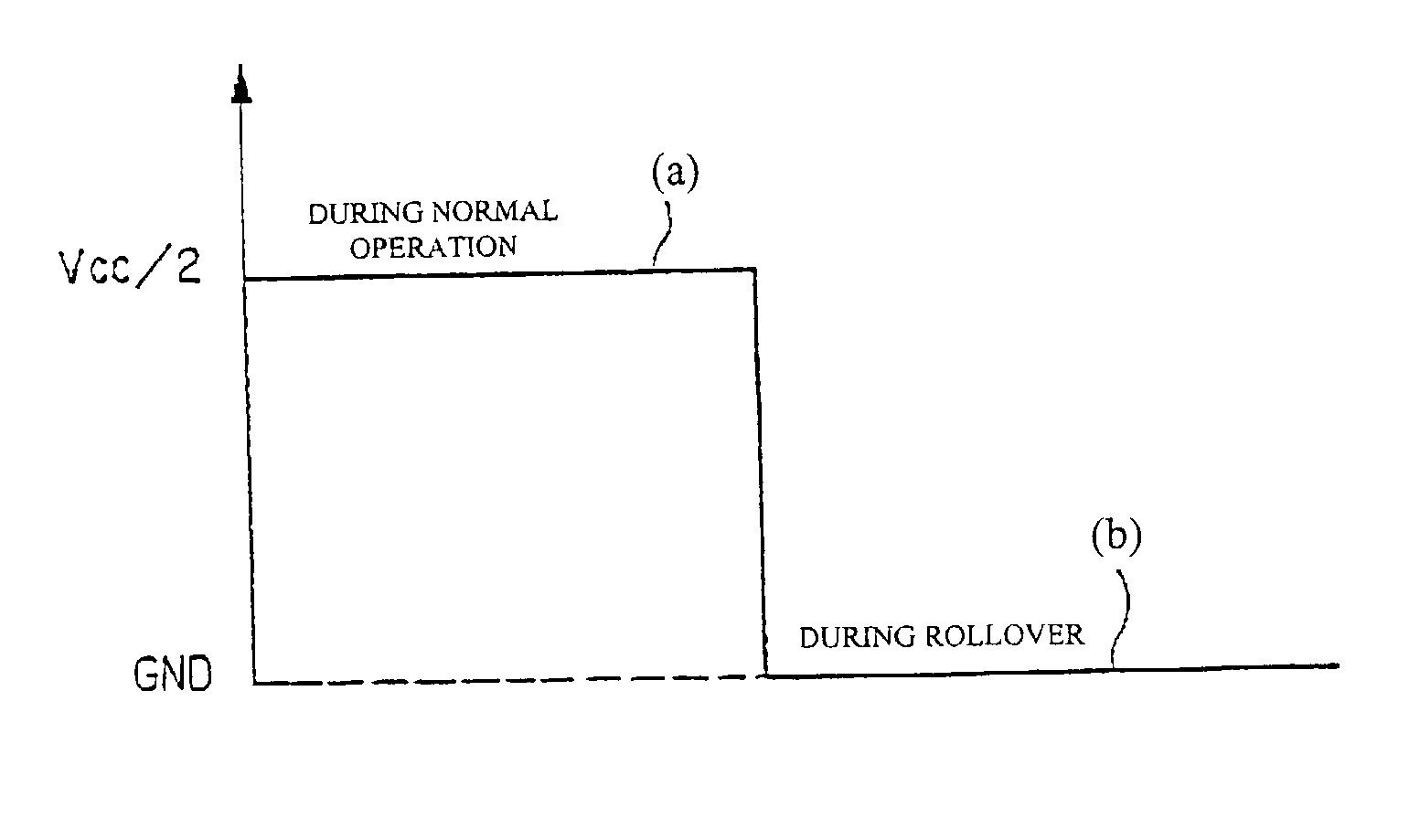
[0100] When such a rollover detecting sensor S2' is used, normally (when there is no rollover) the low level signal indicated by (c) in FIG. 10 is ...


PUM


Abstract

A vehicle-mounted four cycle engine control device which includes an oil pressure detecting sensor that detects a pressure of lubricating oil circulated under pressure in an engine. An oil pressure detecting sensor failure judging system judges whether or not the oil pressure detecting sensor has failed. An engine speed judging system judges whether or not a speed of the engine is equal to or above a predetermined engine speed. A pressure state judging system judges whether or not the lubricating oil pressure detected by the oil pressure detecting sensor continues to be in a state of being lower than a predetermined reference pressure for a predetermined time interval or more. An engine control system reduces the engine speed when it is respectively judged by each of the judging systems that the oil pressure detecting sensor has not failed, that the engine speed is equal to or above the predetermined engine speed, and that the lubricating oil pressure continues to be in a state of being lower than the reference pressure for a predetermined delay time or more.

Description

[0001] The present application claims priority under 35 U.S.C. .sctn.119 of Japanese Patent Application Nos. 2001-371665 filed on Dec. 5, 2001, and 2001-303018 filed on Sep. 28, 2001, the disclosures of which are expressly incorporated by reference herein in their entireties.[0002] 1. Field of the Invention[0003] The present invention relates to a four-cycle engine control device mounted in a vehicle such as a motorcycle, snow vehicle, or aquatic motorcycle.[0004] 2. Description of the Related Art[0005] Conventionally, an oil pressure warning lamp driver circuit 1 of the kind shown in FIG. 13 is connected to a four cycle engine mounted in a snow vehicle, for example.[0006] This oil pressure warning lamp driver circuit 1 includes an oil pressure switch 2 which is turned OFF when the pressure of lubricating oil circulating within the engine body (not shown) is higher than a reference pressure and turned ON when this pressure is lower than the reference pressure, and an oil pressure wa...

Claims


Application Information

Patent Timeline
Patent Type & Authority Applications(United States)
IPC IPC(8): F01M1/22F02D45/00
CPCF01M1/22
Inventor IYODA, EIICHISHIBANO, KEN
Owner SUZUKI MOTOR CORP
Why Eureka
Try Eureka