Apparatus, system, and method for detecting and reimpressing electrical charge disturbances on a drill-pipe

a technology of electrical charge disturbance and apparatus, applied in the field of apparatus, can solve the problems of high power consumption, significant time-consuming installation, recovery, and high power consumption, and achieve the effects of prolonging battery life, desensitizing data reception, and lowering battery power consumption

Inactive Publication Date: 2003-06-05
RYAN ENERGY TECH
View PDF25 Cites 37 Cited by
  • Summary
  • Abstract
  • Description
  • Claims
  • Application Information

AI Technical Summary

Benefits of technology

0054] The disclosed invention solves a number of problems with the prior art by eliminating cables, lowering battery power consumption (to extend battery life), desensitizing data reception to the composition of the formation, desensitizing the signal transferring apparatus to noise thereby permitting the use of simpler electronics and simpler signal processing techniques, and simplifying both installation in and removal from any drilling well whether in exploration or production mode. This invention teaches how a drill-string may be used inexpensively as a low bandwidth transmission line to guide borehole data to the surface. More particularly, the invention teaches a method of using a system employing an apparatus that detects, stores, and resends signals comprising a series of transient disturbances of the electrical surface charge on a drill-pipe from which data may be extracted.

Problems solved by technology

Since the 1930's when U.S. Pat. No. 1,927,664 was issued to Karcher, problems, described in the prior art, were associated with both the "mud pulse" fluid and the acoustic means of transferring information.
However, as wells become deeper and also when the formation being drilled through becomes more conductive, the traditional EM means will eventually no longer be effective in radiating sufficiently to reach the surface if relying on passage through the formation--because the EM energy dissipates in the formation to a level below the detection threshold at the surface.
b) requires significant time to install, recover, and periodically replace
a) high power consumption (short battery life) passing sufficient current across the gaps in order to radiate sufficient energy from those gaps; and
And, the ExMRTx suffer four primary disadvantages:
a) high power consumption (short battery life) passing sufficient current across the gaps in order to radiate sufficient energy from those gaps; and
b) sensitivity to the composition of the geologic formation between the borehole and the surface sensing point (electrode);
c) high noise sensitivity demanding more complex electronics and signal processing; and
d) inability to deploy in exploration mode (i.e. only applies to "operational" wells).
In fact in studies conducted by the US Navy using extremely low frequency ("ELF")--conventional "radio" techniques based on electromagnetic radiation have been determined to be impractical in electrically conductive sea water.
This is significant because the prior art reviewed fails to address the electrical characteristics of drilling mud, which has some similarity to sea water.
The US Navy has also determined that generating a "useful signal" using the traditional radiating antenna model of EM communications requires an unusually long physical antenna because the antenna length is inversely proportional to the frequency.
Since most EFT prior art patents teach operation in the 2-10 Hz range, the above suggests that describing the average drill-string or any of its components as an "antenna" is likely not appropriate and possibly misleading.
Consequently, in the ELF range, the relatively low acceleration of (long wavelength) charge in the current flowing across insulating gaps results in low levels of radiation.
d) a lengthy and expensive insulated conductor.
The chain of dipoles model is also consistent with a cylindrical "antenna" that is broken down into a series of short segments each being a separate circuit that results in an incremental loss feeding into the next segment (circuit).
In a design that channels the displacement effect directly up the (highly conductive) metal drill-pipe, the attenuation takes place over a greater distance permitting detection over a longer range, requiring fewer repeaters and shorter bursts, also resulting in lower power consumption.
None of the EFT prior art recognizes the electrode nature of the drill-pipe or offers a rigorous scientific analysis of the influence of the ionic solution (drilling mud) inside as well as surrounding the pipe and filling the annulus external to it.
'461) typically utilize electromagnetic coils, which coils make repeaters 34,36 large, bulky, relatively expensive, and relatively high in power consumption (shortening their battery life).
Further, due to such repeaters being mounted on the exterior of a pipe string, they are only suited to operational wells and not for MWD ("measurement while drilling").
'990 are very sensitive to noise resulting in the need to use both more expensive electronic components and more sophisticated signal processing in their implementation.
Moreover, the signal distortion in schemes such as that of U.S. Pat. No.
'990, which amplify and repeat the subject signal, without a "silence time" delay, build in a cumulative error unlike the detection and replacement scheme inherent in a silence time based design.
Such patent teaches the use of insulated wires, which are problematic for the reasons given above

Method used


Image

  • Apparatus, system, and method for detecting and reimpressing electrical charge disturbances on a drill-pipe
  • Apparatus, system, and method for detecting and reimpressing electrical charge disturbances on a drill-pipe
  • Apparatus, system, and method for detecting and reimpressing electrical charge disturbances on a drill-pipe

Examples


Embodiment Construction

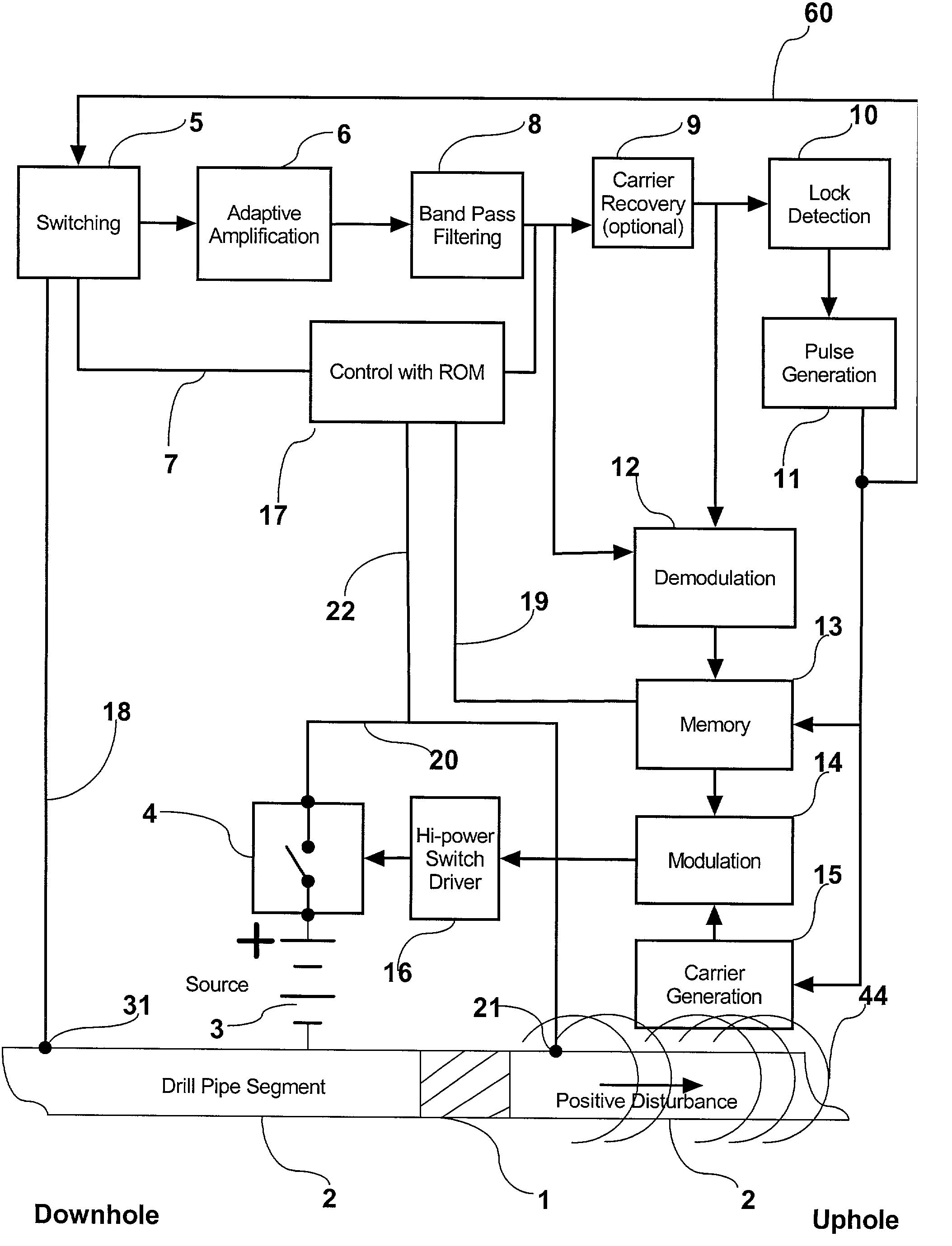
[0075] Reference is to be had to FIGS. 1 & 2, wherein like items are identically numbered.

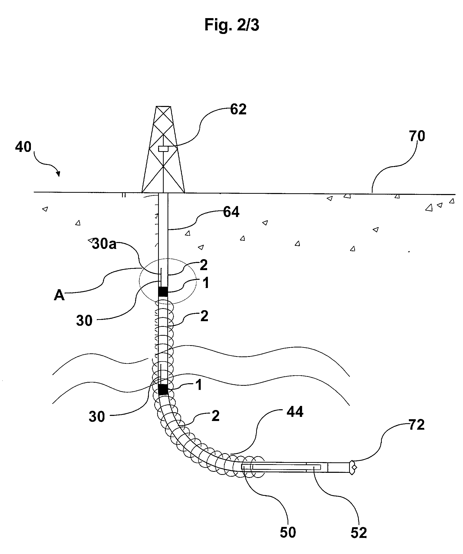
[0076] FIG. 2 shows a system 40 of the present invention, wherein a signal repeater 30 of the present invention is employed in order to receive a pre-modulated electrical signal 44 at insulating gap 1 in drill pipe string 2 that extends below the earth's surface 70. Signal 44 is generated by an off-the-shelf Downhole Sending Unit ("DSU") 50, which itself comprises a Code Sequence Generator ("CSG") (not shown) and a power source, typically a battery (not shown). DSU 50 generates signal 44 using data supplied to it by an off-the-shelf instrumentation package, such as a direction and inclination sensing device (i.e. a "D & I" unit) 52 commonly employed, in downhole drilling to provide information to a receiver 62 located above the earth's surface 70, to permit a drill operator to be apprised of the direction and inclination of the drill bit 72 at the lower most extremity of the well 64 as drilling...


PUM


Abstract

A signal repeater, a system utilizing one or more signal repeaters, and a method fordetecting a transient disturbance in the surface charge on drill pipe, which system, apparatus and method are collectively used to transfer data from deep-well and high-conductivity formation subterranean environments to a point nearer to the surface. The signal repeater comprises a housing that is securably mountable to the interior of a pipe-string disposed in a wellbore, which repeater receives and stores electrical signals for resending at an appropriate time.

Description

FIELD OF THE INVENTION[0001] The present invention relates to an apparatus, system, and method for the transfer of information from locations deep under the surface of the earth to locations nearer to the surface of the earth, and vice versa, and more particularly to a system, method, and a signal repeater device for transmitting signals along a drill pipe.BACKGROUND OF THE INVENTION[0002] Since the 1930's when U.S. Pat. No. 1,927,664 was issued to Karcher, problems, described in the prior art, were associated with both the "mud pulse" fluid and the acoustic means of transferring information. These problems have, to a substantial extent, been solved most in most shallow well applications by using higher reliability electromagnetic ("EM") means by which electrical energy radiates through the surrounding soil formation up to the surface. However, as wells become deeper and also when the formation being drilled through becomes more conductive, the traditional EM means will eventually n...

Claims


Application Information

Patent Timeline
Patent Type & Authority Applications(United States)
IPC IPC(8): E21B47/26E21B47/13H04B3/36
CPCE21B47/122E21B47/124E21B47/26E21B47/13
Inventor KORO, VICTOR
Owner RYAN ENERGY TECH
Why Eureka
Try Eureka