Electrical discharge devices and techniques for medical procedures

a technology of electric discharge device and medical procedure, applied in the field of electrosurgical instruments, can solve the problems of significant collateral damage to tissue volumes adjacent to the targeted site, explosion of water to damage or destroy tissue, and inefficient volumetric tissue removal without extensive collateral damage, and achieve the effect of enhancing an electron avalanche in plasma

Inactive Publication Date: 2003-07-03
RELIGN CORP
View PDF1 Cites 137 Cited by
  • Summary
  • Abstract
  • Description
  • Claims
  • Application Information

AI Technical Summary

Benefits of technology

0075] FIG. 18 is a view of an alternative embodiment of working end for practicing the method of FIG. 17 in which multiple MCP's are arranged in a chevron pattern to further enhance an electron avalanche in plasma volumes.

Problems solved by technology

In other words, the energy sources elevate the temperature of water in intra- and extracellular spaces to above 100.degree. C. thereby explosively vaporizing water to damage or destroy the tissue.
The drawback to such purely thermally-mediated ablations is significant collateral damage to tissue volumes adjacent to the targeted site.
The conventional long-pulse laser systems outside the UV range, wherein long-pulse is defined as a system operating in a range of 10's of nanoseconds to microseconds in pulse duration, have been found to be inefficient in volumetric tissue removal without causing extensive collateral damage.
These collateral effects propagate through surrounding tissues as heat, and perhaps mechanical shock waves, which manifest themselves as undesirable collateral damage.
Ablation or damage occurs by conventional heat deposition resulting in vaporization, melting, or fracture of the structure.
It has been found that ablation thresholds generally require relatively long pulse durations, which in turn are the source of undesirable collateral photothermal (or photomechanical) damage.
While UV photonic energy delivery can reduce collateral damage in tissue ablation, there are numerous disadvantages that limit the applicability of UV lasers to biomedical procedures.
First, UV photonic energy delivery cannot be easily delivered to a targeted site of a body structure in a fluid environment (e.g., thrombus in a blood vessel) since intervening fluid may absorb energy rather than the target site.
Second, the desired lack of collateral damage in UV ablation is known to occur when a single pulse of UV photonic energy irradiates a tissue surface.
However, when the UV pulse repetition rate exceeds about 5 to 10 Hz, considerable photothermal collateral damage (as well as photomechanical collateral damage) has been observed.
Thus, UV ablation generally may result in low volumetric removals of tissue surfaces per unit of time.
Such an Rf spark created between the active electrode and the tissue will cause localized damage and ablation at the discharge conduction site at the surface of the tissue.
In other words, the spark causes very high energy densities at the random location that the tissue interfaces the bubble 3 which in turn results in intense heat that disrupts and ablates a site on the tissue surface.
In any event, on a ns or ms time-scale, it is clear that the dimensions and energy distribution characteristics of energy delivery are uncontrolled and random.
While conventional electrosurgical ablation and Coblator.TM. type ablations are suitable for various procedures, the following characteristics common to both types of ablation prevent the possibility of more precise ablations with such prior art systems
(vi) the amount of energy applied per time interval at an energy deposition site is uncontrolled;
(ix) the conductive or insulative characteristics of media between the active electrode and the targeted site, at a micro-scale, are uncontrolled,

Method used


Image

  • Electrical discharge devices and techniques for medical procedures
  • Electrical discharge devices and techniques for medical procedures
  • Electrical discharge devices and techniques for medical procedures

Examples


embodiment 205

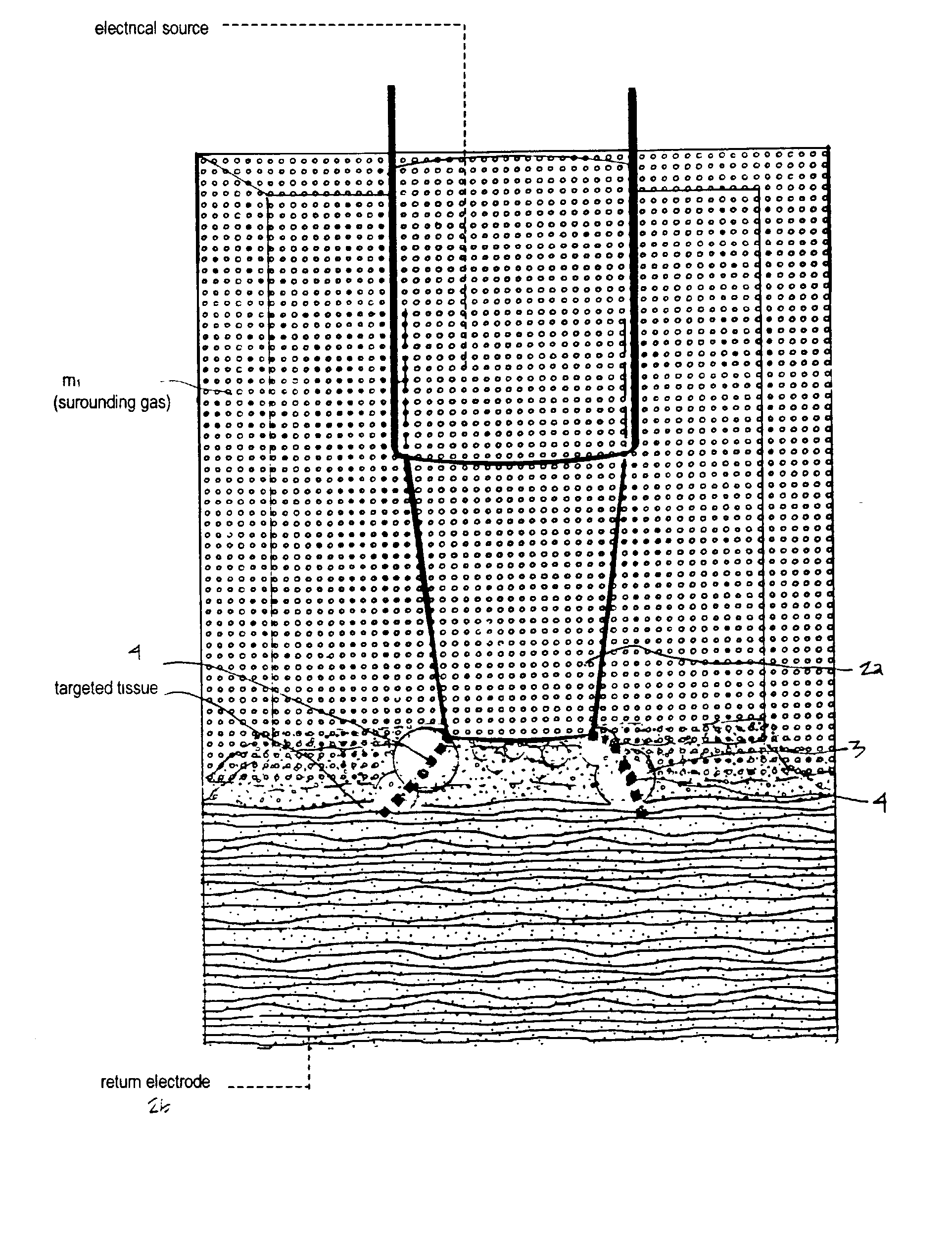
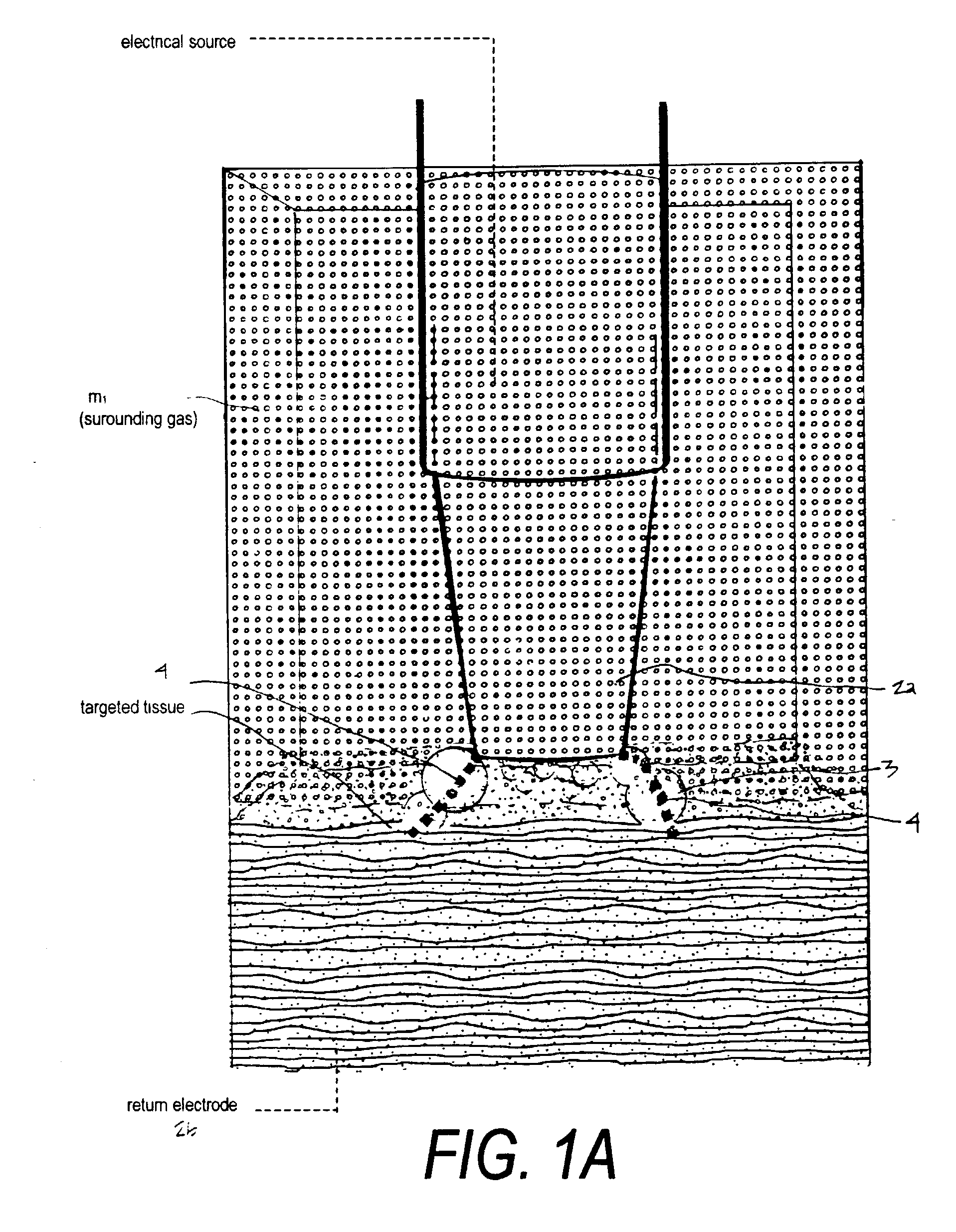
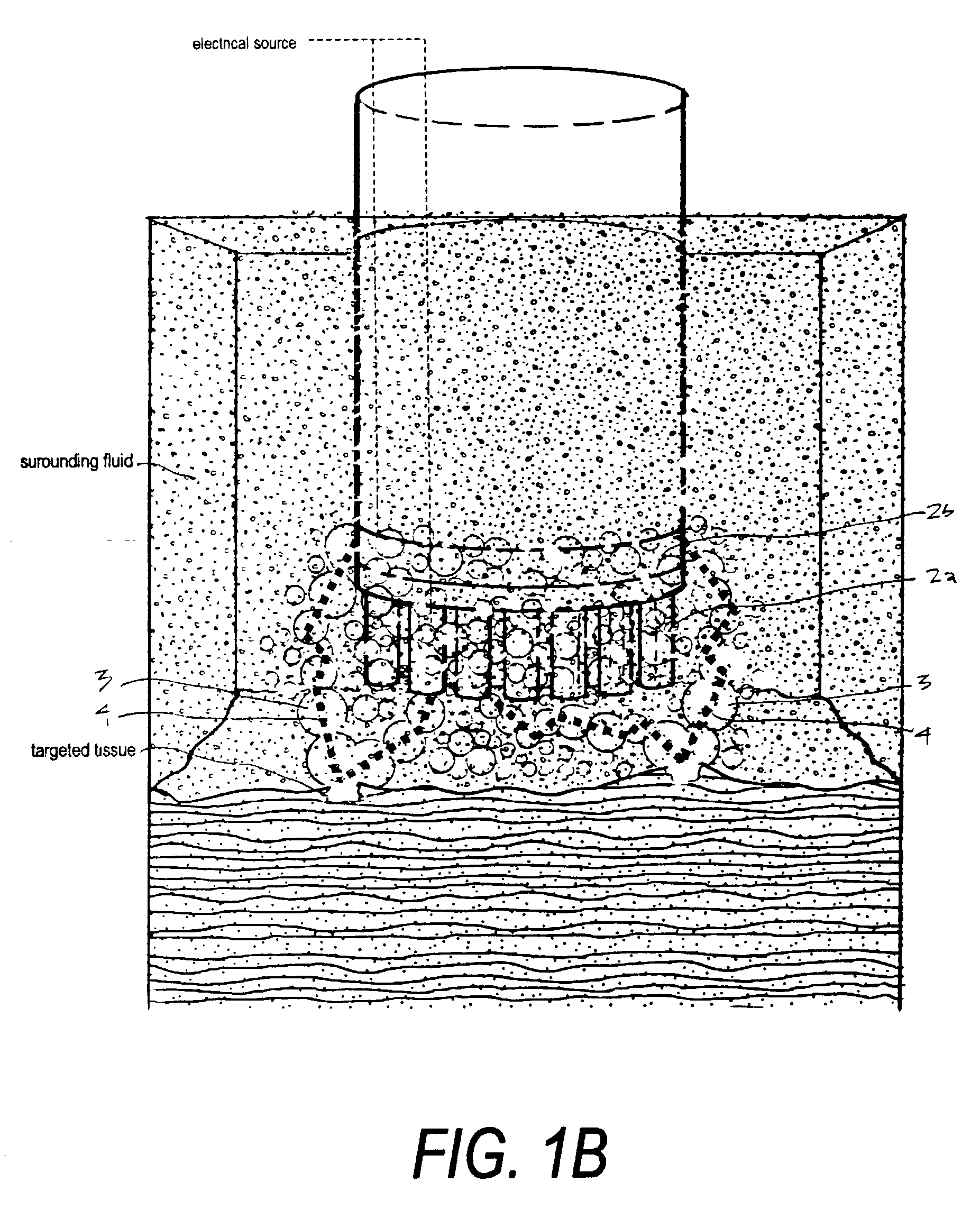
[0122] In a previous part of this disclosure (see "Summary and Objects of the Invention"), a number of processes were described to cause, induce or develop ionization of a captured neutral gas volume (or bubble), and thereafter terminate ionization of the gas, in an interface between a probe working end and a targeted site ts. Such an instantaneously and independently ionized gas volume can then cause an intense application or arc of electrical energy from an electrode to the targeted site ts across the gas volume to volumetrically remove surface layers of an anatomic structure. Several ionization processes were described above, viz., photoionization (PI), field ionization (FI), thermal ionization (TI) and the ionization of surface analytes from a solid material. In this Type "C" embodiment 205, the use of independent field ionization (FI) means is described as an option in Section V(C) below and at times referred to as the first energy source. In addition, a working end carrying a ...

embodiment 400

[0152] FIGS. 22A-22B below illustrate a Type "E" embodiment 400 that provides an additional energy delivery mode that has been found to optimize the formation, character and dimension of gas bubbles in the interface between the working surface 415 and the targeted tissue.

[0153] More in particular, it has been found the application of vibrational energy to, and about, the working surface can increase the efficiency of the electrical energy application across the transient gas volume or bubbles that are formed between the working surface and the targeted tissue. In one embodiment, referring to FIG. 22, the instrument body 410 extends to a working surface 415 that, for convenience shows a single media entrance channel 422 but a plurality of microchannel entrance ports are more practical for a typical dimension working end as shown in FIGS. 12, 13, 19C, 19C and 20. A remote source of a selected gas as described previously is operatively coupled to the instrument to provide flow through ...


PUM


Abstract

A medical instrument coupled to first and second energy means and a computer controller for the controlled volumetric removal of thin tissue layers. The system provides a source for introducing a gas to controllably form and capture transient gas volumes in a microchannel structure at the working surface of the instrument that interfaces with a targeted tissue site. Each of the microchannel features of the working surface carries an electrode element coupled to the electrical source. The energy may be applied to the targeted site in either of two modes of operation, depending in part on voltage and repetition rate of energy delivery. In one mode of energy application, electrical potential is selected to cause an intense electrical arc across the transient ionized gas volumes to cause an energy-tissue interaction characterized by tissue vaporization. In another preferred mode of energy delivery, the system applies selected levels of energy to the targeted site by means of an energetic plasma at the instrument working surface to cause molecular volatilization of surface macromolecules thus resulting in material removal. Both modes of operation limit collateral thermal damage to tissue volumes adjacent to the targeted site. Another preferred embodiment provides and an ultrasound source or other vibrational source coupled to the working end to cause cavitation in fluid about the working end.

Description

[0001] This application is a Continuation-In-Part of U.S. patent application Ser. No. 09 / 614,163 filed Jul. 11, 2000 (Docket S-QP-006) titled Electrical Discharge Devices and Techniques for Plasma-Assisted Skin Resurfacing which is a Continuation-In-Part of U.S. patent application Ser. No. 09 / 317,768 filed May 24, 1999 (Docket No. S-QP-002) titled Photoionized Gas Enabled Electrical Discharge Technique for Plasma-Mediated Cold Tissue Ablation. This application also is related to U.S. Provisional Patent Application Ser. No. 60 / ___,___, filed Jun. 2, 2000 (Docket No. S-QP-005) titled Electrical Discharge Medical Devices and Techniques for Plasma-Assisted Material Removal. All of the above applications are incorporated herein by this reference.[0002] 1. Field of the Invention[0003] The invention is related to electrosurgical instruments and techniques for precision application of energy to tissue, and more particularly to a system for thin layer ablation. More in particular, the workin...

Claims


Application Information

Patent Timeline
Patent Type & Authority Applications(United States)
IPC IPC(8): A61B18/00
CPCA61B17/22004A61B2018/1213A61B2017/22008A61B18/042
Inventor TRUCKAI, CSABASHADDUCK, JOHN H.
Owner RELIGN CORP
Why Eureka
Try Eureka