

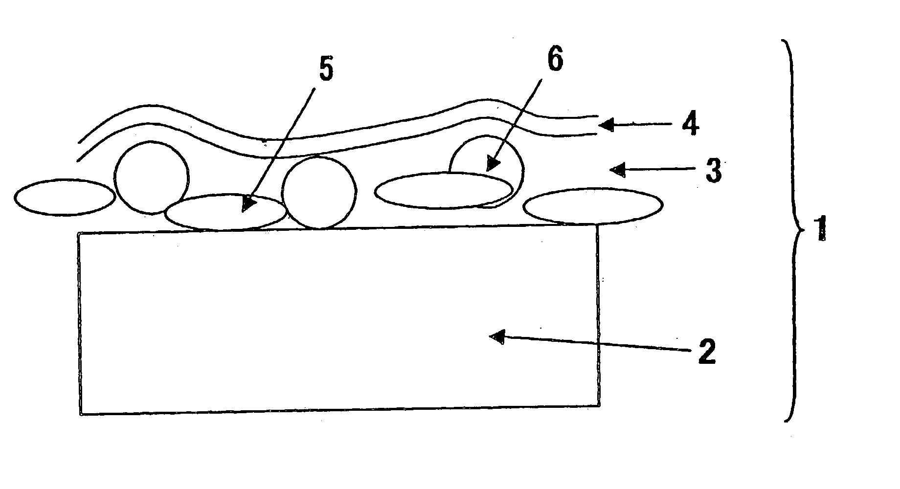
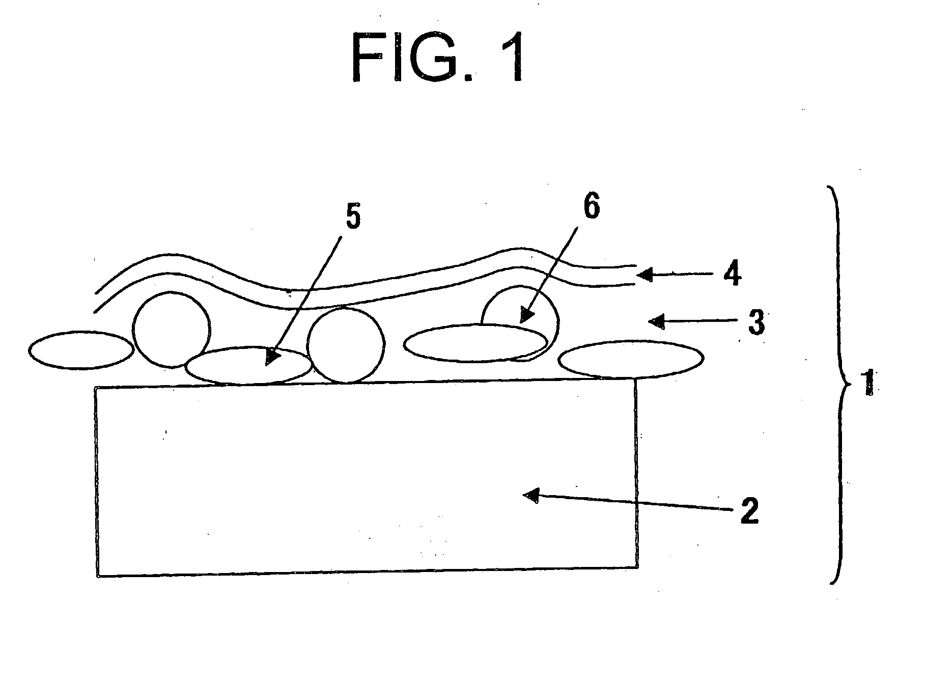
Diffusing film comprising transparent resin and scatterers
a technology of diffuser and transparent resin, which is applied in the direction of instruments, polarising elements, optical elements, etc., can solve the problems of inability to fully improve image quality, high cost, and difficult mass production, and achieve the effect of controlling surface roughness, improving viewing angle character, and transmitting imag
- Summary
- Abstract
- Description
- Claims
- Application Information
AI Technical Summary
Benefits of technology
Problems solved by technology
Method used
Image

Examples
example 2
[0258] As the transparent resin constituting the scattering layer, 150 weight parts of 65 wt. % zirconium oxide-dispersed gelatin was added in water. The obtained liquid was applied to form a layer having the refractive index of 1.64.
[0259] To the above liquid, 8.5 weight parts of crosslinked polystyrene beads (SX350, Soken Kagaku Co., Ltd.; particles size: 3.5 .mu.m; refractive index: 1.61) as the matting particles and 20 weight parts of transparent monomer (a mixture of 43 weight parts of transparent resin [DPHA, Nippon Kayaku Co., Ltd.] and 5 weight parts of hardening initiator [Irgacure 184, Ciba-Geigy]) were mixed. The solid content of the prepared liquid was controlled with water at 50%. The thus-prepared liquid was emulsified by means of a dissolver at 10,000 rpm for about 15 minutes. The prepared emulsion was applied on a triacetyl cellulose film (TD-80U, Fuji Photo Film Co., Ltd.) to form a layer having the dry thickness of 3.5 .mu.m. The layer was dried, and then exposed t...
example 3
[0265] The above-prepared coating solution was applied on the scattering layer of the diffusing film (HKF-01) by means of a wire-bar coater, dried at 80.degree. C., and further heated at 120.degree. C. for 10 minutes to crosslink. Thus, a low refractive index layer (thickness: 0.096 .mu.m) was formed to produce an anti-reflection film (HKHB-01).
example 4
[0266] The coating solution for low refractive index layer was applied on the scattering layer of the diffusing film (HKF-02) by means of a wire-bar coater, dried at 80.degree. C., and further heated at 120.degree. C. for 10 minutes to crosslink. Thus, a low refractive index layer (thickness: 0.096 .mu.m) was formed to produce an anti-reflection film (HKHB-02).
COMPARISON EXAMPLE 1
[0267] As the transparent resin constituting the scattering layer, 100 weight parts of UV curable resin (Desolite Z-7526, JSR Co., Ltd.; refractive index: 1.51) was used. To the resin, 12 weight parts of benzoguanamine-melamine-formaldehyde beads (Nippon Catalyst Co., Ltd.; particles size: 0.5 .mu.m; refractive index: 1.68) as the transparent fine particles and 11 weight parts of crosslinked polystyrene beads (SX350H, Soken Kagaku Co., Ltd.; particles size: 3.5 .mu.m; refractive index: 1.61) were mixed. The solid content of the prepared liquid was controlled with methyl ethyl ketone / acetone (40 / 60) at 50%. ...
PUM
 Abstract
Description
Claims
Application Information