Method and apparatus for generation of molecular beam

a molecular beam and molecular beam technology, applied in the direction of particle separator tube details, instruments, separation processes, etc., can solve the problems of ineffective molecular beam generation method for liquid or solid samples with high molecular weight, and ineffective second conventional method for producing ion beams for neutral molecules

Inactive Publication Date: 2003-09-11
NAT INST OF INFORMATION & COMM TECH
View PDF45 Cites 18 Cited by
  • Summary
  • Abstract
  • Description
  • Claims
  • Application Information

AI Technical Summary

Problems solved by technology

However, the first conventional method for generation of a molecular beam is ineffective for a liquid or solid sample with a high molecular weight.
The second conventional method to produce an ion beam is ineffective for neutral molecules, as it can be applied only for ionized molecules.

Method used


Image

  • Method and apparatus for generation of molecular beam
  • Method and apparatus for generation of molecular beam
  • Method and apparatus for generation of molecular beam

Examples


example 2

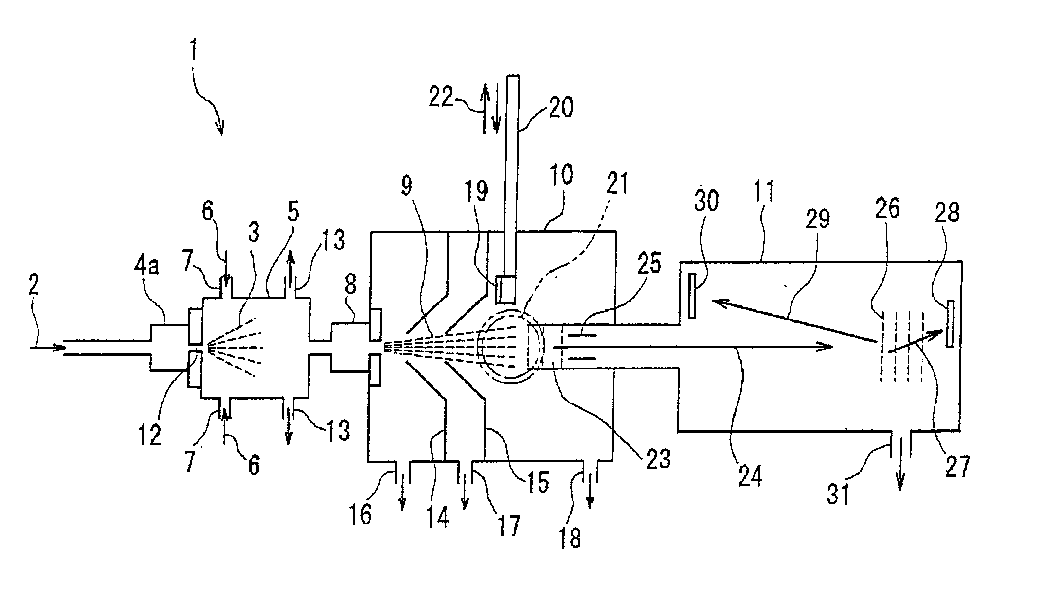
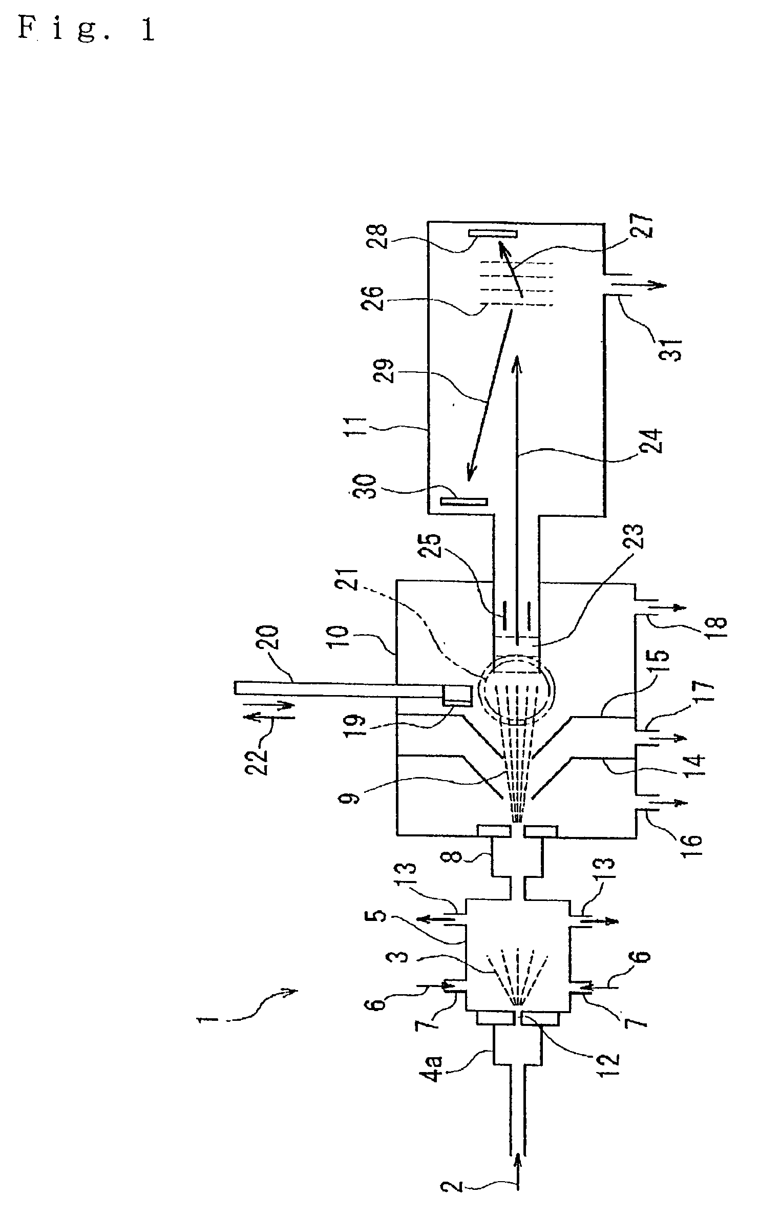
[0080] A pulsed laser was applied to irradiate a molecular beam of the sample molecules (9) through the viewing-ports (21) of the high vacuum chamber (10) in the apparatus (1) as illustrated by FIG. 1. The molecular beam of the sample molecules (9) is cooled to extremely low temperatures due to the adiabatic expansion, resulting the distributions of the rotational states and the vibrational states are simplified. It is possible to obtain spectroscopic information by irradiating the cooled molecular beam with the laser beam.

example 3

[0081] A substrate was located on the path of the molecular beam of the functional molecules used in Example 1 to deposit them on the substrate. After the deposition, a pulsed laser was applied to irradiate the functional molecules deposited on the substrate (9) through the viewing-ports (21) of the high vacuum chamber (10) in the apparatus (1) as illustrated by FIG. 1, in order to investigate an electronic structure of the functional molecules on the substrate.

example 4

[0082] Within the vacuum chamber (10) of the apparatus (1) as illustrated in FIG. 1, another molecular beam source was provided. With such an arrangement, a collision between the sample molecular beam (9) and another molecular beam caused the chemical reaction.

[0083] Effect of the Invention

[0084] The present invention enables to generate a molecular beam from a sample solution of wide range of molecules at a room temperature, particularly for the neutral molecules which can be easily decomposed by heating at a high temperature or the neutral molecules which can not be sublimated or vaporized by heating at a high temperature, as long as the sample solution can be prepared. The sample molecules and the inclusion cluster contained in the neural molecular beam can be excited or photo-ionized, for example, by using laser beams. Therefore it is possible to perform the mass spectroscopy studies and other spectroscopic analyses. It is also possible to deposit the neutral molecules on a subs...


PUM

PropertyMeasurementUnit
diameteraaaaaaaaaa
diameteraaaaaaaaaa
lengthaaaaaaaaaa

Abstract

Here is disclosed a method for generation of a molecular beam from a sample solution, comprising steps of operating a spray-in device to introduce the sample solution in atomized state into a spray chamber, impinging a suitable gas on the sample solution in atomized state or heating the sample solution in atomized state to generate solute molecules deprived of solvent molecules, and then ejecting these solute molecules through an orifice into a low air pressure chamber. The apparatus as well as the method according to the present invention enable to generate a molecular beam for a variety of molecules, particularly for the neutral molecules which can be decomposed by heating at a high temperature or those which can not be sublimated or vaporized even by heating at a high temperature, as long as the sample solutions are prepared. Due to the method as well as the apparatus according to the invention, it is possible to conduct the mass spectroscopy studies and also other spectroscopic analyses about the molecules and the molecular clusters containing in the molecular beam generated in this manner, for example, by irradiating laser beams. It is possible to also possible to deposit the molecules on a substrate.

Description

TECHNICAL BACKGROUND[0001] The present invention relates to a method to generate a neutral molecular beam of sample molecules by multistage spraying of the sample solution and further to an apparatus that actualizes this method.[0002] The conventional method for generating a molecular beam comprises steps of: mixing gaseous sample molecules with rare gas atoms; introducing the mixed gas through a nozzle directly into vacuum where the mixed gas is adiabatically expanded to form a supersonic jet flow; and guiding this supersonic jet flow through a skimmer to form a molecular beam. For a sample in form of liquid or solid, the method similar to what described above for the gaseous sample is carried out after heating the sample so as to vaporize or to sublime.[0003] The sample molecules in the supersonic jet flow are adiabatically expanded in vacuum, so that they are cooled at a temperature of several Kelvins for rotation and at a temperature of several dozens of Kelvins for vibration. C...

Claims


Application Information

Patent Timeline
Patent Type & Authority Applications(United States)
IPC IPC(8): G01N27/62B01D59/44G01N1/00G01N1/28G01N21/27G01N27/64G01N35/08G01N37/00H01J27/00H01J49/00H01J49/02H01J49/04H01J49/10H05H3/02
CPCH01J49/0422H01J49/162H01J49/0445
Inventor YAMADA, TOSHIKISHINOHARA, HIDENORIMASHIKO, SHINROKIMURA, KATSUMI
Owner NAT INST OF INFORMATION & COMM TECH
Why Eureka
Try Eureka