Method in connection with engine control

Inactive Publication Date: 2003-09-18
ALTRONIC
View PDF6 Cites 49 Cited by
  • Summary
  • Abstract
  • Description
  • Claims
  • Application Information

AI Technical Summary

Benefits of technology

0007] The proposed system leads to improved performance and increased functionality compared to existing solutions for engine control, and is conceptually simpler and therefore also more cost efficient.
0008] According to a further aspect of the invention model-based diagnosis is used. B

Problems solved by technology

In engine control, it is a challenge to keep engine efficiency and combustion stability as high as possible while minimising emissions.
Calibration of an engine management system is therefore typically a very time consuming and expensive task and accordingly there is a need for other control possibilities, especially since the requirements are continuously augmented.
However, known systems which use continuous measurements for engine control all show some drawbacks, as will be explained later.
However, these known engine control systems al

Method used


Image

  • Method in connection with engine control
  • Method in connection with engine control
  • Method in connection with engine control

Examples


Embodiment Construction

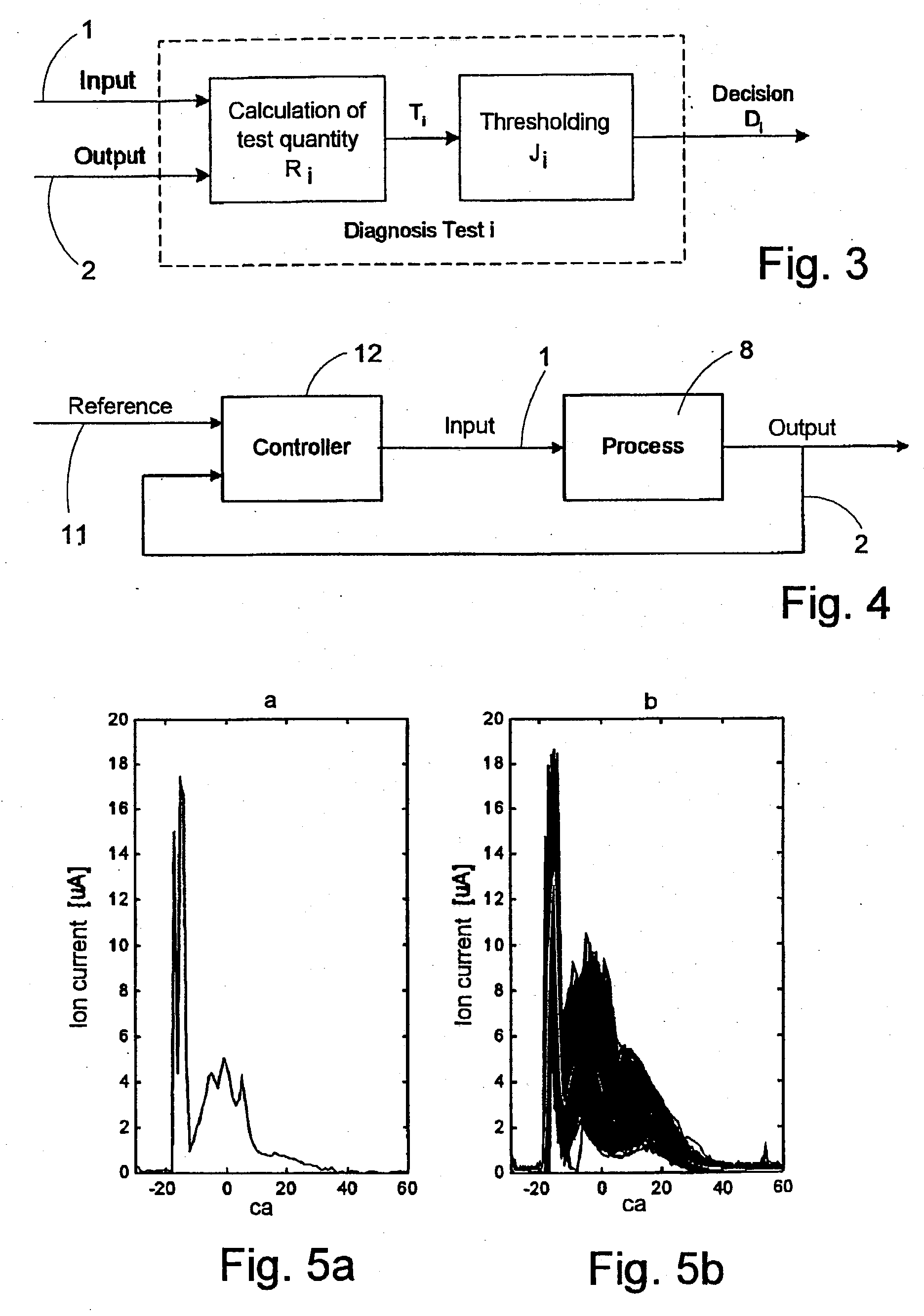
[0038] To further explain the concept behind the classification and the parameter estimation according to the invention, there is now presented an example where the ionisation current signal is used as combustion feedback signal. The ionisation current (and also the cylinder pressure) is directly coupled to the combustion and contains all necessary information on the combustion quality. Hence it is well suited for engine control purposes.

[0039] Modelling of Ionisation Current Signals

[0040] FIG. 5a-b shows two examples of ionisation current cycle-to-cycle variations and average behaviour. FIG. 5a shows a single ionisation current curve and FIG. 5b shows a number of consecutive cycles and--inverted--the average of these curves.

[0041] Several studies, e.g. Nielsen and Eriksson (1998) according to the above, have shown that the ionisation currents can be effectively modelled using a parametric radial basis function network. In this example there is considered models of the form:

I.sup.(....


PUM


Abstract

This invention relates to a method in connection with engine control, wherein a combustion feedback signal is derived by measuring one or more combustion related parameters during a chosen time period of a first combustion cycle, for control of a possible fault, wherein at least one reference feature for said parameters has been determined previously, and comparing said measured combustion feed back signal with said reference feature for automatic adaptation of at least one combustion related variable during a forthcoming combustion cycle wherein at least one reference features for each one of at least two different fault situations having been determined previously, and that a diagnosis 3 of said first combustion cycle is performed on the basis of said combustion feedback signal being processed and compared (T1-Tn) with each one of said reference features, the result of which is analysed by a decision logic, whereafter a diagnosis (D) is established by means of which one or more variables in a forthcoming combustion cycle is/are regulated in dependence of the outcome (D) of said diagnosis, thereby achieving fault tolerant engine control.

Description

[0001] The present invention relates to a novel method in connection with a fault tolerant engine control system, wherein a combustion feedback signal is derived by measuring, in a combustion chamber, one or more combustion related parameters during a chosen time period of a first combustion cycle. For the corresponding time period, an ideal reference signal for said parameters has been previously determined. The method is primarily intended for control of Otto engines or Diesel engines.[0002] In engine control, it is a challenge to keep engine efficiency and combustion stability as high as possible while minimising emissions.[0003] Control of Otto engines basically amounts to controlling three primary variables: ignition timing and fuel and air injected into the cylinder. For the two latter both the mass and the timing are important and these are controlled separately using different actuators such as the throttle, the fuel injectors, and the intake valves depending on engine desig...

Claims


Application Information

Patent Timeline
IPC IPC(8): F02D35/02F02D41/14F02D41/22
CPCF02D35/021F02D35/023F02D41/1401F02D35/027F02D2041/1433Y02T10/40F02D35/024F02D41/22F02D41/1406
Inventor NYTOMT, JANFORSELL, URBAN
Owner ALTRONIC
Why Eureka
Try Eureka