Fiber-coupled vertical-cavity surface emitting laser

a technology of fiber-coupled vertical cavity and laser, which is applied in the direction of semiconductor lasers, instruments, optical elements, etc., can solve the problems of relative complex fabrication and alignment, device susceptible to potential misalignment, thermal effects, shock and vibration, etc., and achieves single-mode operation and increased mode field diameter

Inactive Publication Date: 2003-10-02
LIGHTPATH TECH INC
View PDF13 Cites 39 Cited by
  • Summary
  • Abstract
  • Description
  • Claims
  • Application Information

AI Technical Summary

Benefits of technology

0037] (d) a single-mode optical fiber secured to the multimode fiber, into which seed light from the vertical-cavity surface emitting laser is coupled by the pellet and the graded-index multimode fiber, the single-mode optical fiber including therein an embedded Bragg grating, the Bragg grating reflecting ...

Problems solved by technology

These solutions require relatively complex fabrication and alignment, and are susceptible to thermal effects, shock and vibration, and other environmental factors.
In addition, the air gap between the parts makes the device susceptible to potential misalignment due to environmental factors.
Coupling efficiency is likely to be affected by a size mismatch between the semiconductor component and the fiber.
The multiple discrete components of the coupling device add complexity and cost to the device and require precise alignment and mechanical stability.
As a result, the potential bandwidth and transmission distance dramatically decline...

Method used


Image

  • Fiber-coupled vertical-cavity surface emitting laser
  • Fiber-coupled vertical-cavity surface emitting laser
  • Fiber-coupled vertical-cavity surface emitting laser

Examples


first embodiment

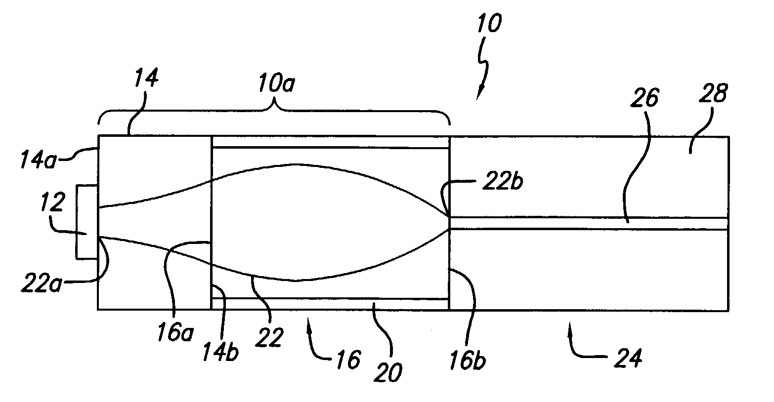
[0049] In the first embodiment, the size of the Gaussian beam 22 of the VCSEL 12 is larger than the mode size of the single-mode fiber 24. The sizes of the VCSEL 12 that can be coupled to the single-mode fiber 24 in this arrangement range from mode size of the single-mode fiber to the maximum beam size in the multi-mode fiber lens 16. The latter is the size of the beam that would be emitted from the end of a 1 / 4 pitch multi-mode fiber 16 if it were illuminated from the single-mode fiber 24 serving as the light source. This maximum beam size is defined by the properties of the multi-mode fiber lens 16, specifically, by the radial profile of the refractive index, or the numerical aperture (NA) of the multi-mode fiber. For lower values of the numerical aperture, the diameter of the Gaussian beam 22 in the multi-mode fiber lens 16 is larger, which widens the range of possible sizes of the VCSEL 12; however, more light energy from the "wings" of the Gaussian beam 22 is lost in the claddi...

second embodiment

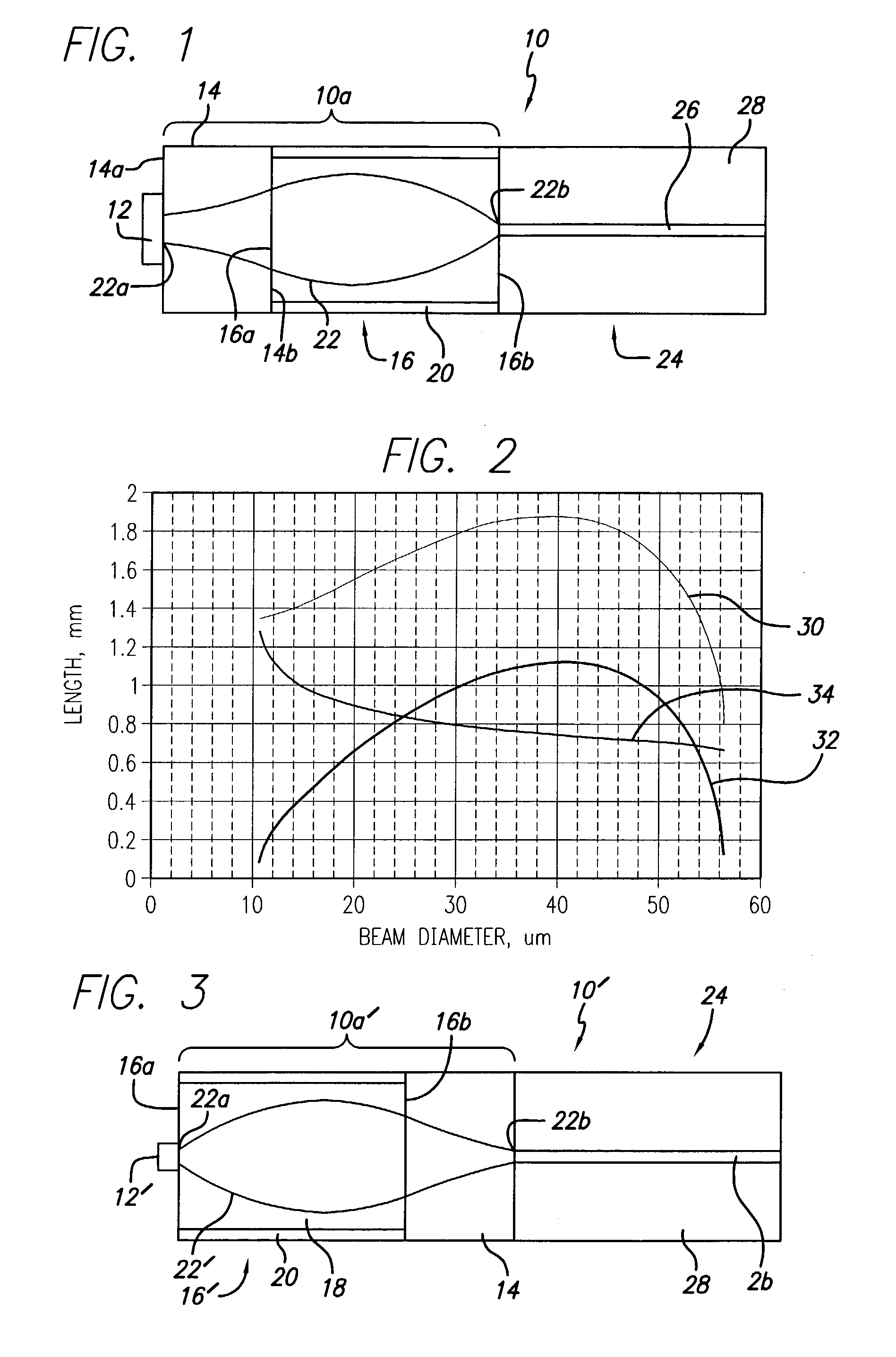
[0053] In the case where the VCSEL 12' has a mode diameter smaller than that of the single-mode fiber 24, then the coupler 10a' may be used, shown in FIG. 3. In this case, the assembly 10' comprises the VCSEL 12' attached to one end 16a of the multi-mode fiber lens 16 by any conventional means. The other end 16b of the lens 16 is attached, preferably fusion spliced, to the pellet 14. The pellet 14 is attached (preferably, fusion spliced) to the single mode fiber (SMF) 24 that receives the optical signal from the VCSEL 12'.

[0054] The structure of the coupler 10a' differs from the first embodiment by the reversed positions of the pellet 14 and the multi-mode fiber lens 16. As a general rule, the lens 16 is adjacent the VCSEL 12' with the smaller Gaussian beam 22' size, whereas the pellet 14 is adjacent the VCSEL 12 with the larger Gaussian beam 22 size.

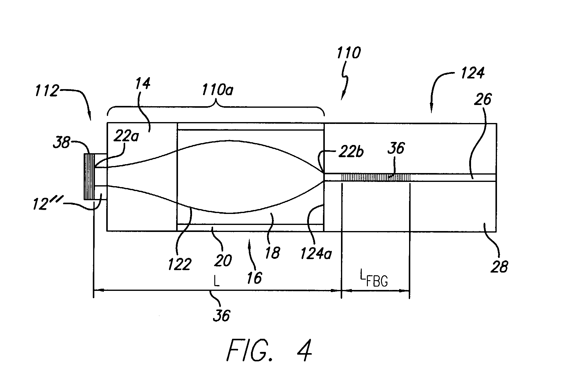
[0055] The numerical aperture of the multi-mode fiber lens 16 will limit the minimum beam size of the VCSEL 12' in the second embodime...


PUM


Abstract

Monolithic structures for coupling either a vertical-cavity surface emitting laser (VCSEL) or a half-cavity vertical cavity surface emitting laser into a single-mode optical fiber are provided. The monolithic structures include a coupler, which comprises a pellet comprising a piece of solid silica glass and a length of graded-index multimode fiber serving as a gradient index lens. Various coupler configurations are provided for handling the cases in which the diameter from the VCSEL is larger or smaller than the diameter of the single-mode fiber. In the case of the half-cavity VCSEL, the single-mode optical fiber including therein an embedded Bragg grating, the Bragg grating reflecting the seed light from the VCSEL, thus providing feedback for laser action. The fiber-coupled laser evidences increased mode field diameter and single-mode operation.

Description

[0001] The present application claims priority based on provisional applications Serial No. 60 / 368,655 and Serial No. 60 / 368,698, both filed Mar. 26, 2002.[0002] The present invention relates generally to vertical-cavity surface emitting lasers, and, more particularly, to the use of such lasers in fiber-optic communications.[0003] Coupling Single-Mode Vertical Cavity Surface-Emitting Lasers to Optical Fibers[0004] Single-mode vertical cavity surface-emitting lasers (VCSELs) in fiber-optic telecommunications offer the advantage of low-cost light sources capable of providing high modulation rates and long transmission distances. The circular beam shape of the laser makes possible butt coupling into standard single mode fiber (SMF) with high efficiency. When the VCSEL diameter differs from that of the fiber, free-space optical components are typically used for coupling. These solutions require relatively complex fabrication and alignment, and are susceptible to thermal effects, shock a...

Claims


Application Information

Patent Timeline
IPC IPC(8): G02B6/42H01S5/00H01S5/026H01S5/183
CPCG02B6/421H01S5/02284H01S5/183H01S5/146H01S5/026H01S5/02251
Inventor GUTIN, MIKHAIL A.
Owner LIGHTPATH TECH INC
Why Eureka
Try Eureka