Nmr resonators optimized for high q factor

a resonator and q factor technology, applied in the field of nmr resonators, can solve the problems of local distortion of the field, compromise of the filling factor, etc., and achieve the effect of reducing the resistance of the rungs, reducing the resistance, and reducing the resistance of the q factor

Inactive Publication Date: 2003-10-16
AGILENT TECH INC
View PDF0 Cites 23 Cited by
  • Summary
  • Abstract
  • Description
  • Claims
  • Application Information

AI Technical Summary

Benefits of technology

[0010] It is yet another advantage of the invention to extend the foregoing to related resonant coil structures.
[0011] A birdcage resonator coil embodying this invention, with which the above and other objects can be achieved, may be characterized as comprising a pair of conductor rings separated from each other along a central axis and a plural number of linearly elongated conductor rungs which extend between the rings and are spaced azimuthally around the central axis, wherein each of the rungs is cross-sectionally so dimensioned that its radial extension (thickness) is at least greater than its azimuthal extension (width). Among other dependencies of Q, a lower resistance for the rungs (inductive elements) leads to a higher Q. Although a larger cross section for these inductive elements will reduce the resistance, the filling factor may be compromised by the intrusion of the radial component of the enlarged cross section. The radial extension outwardly promotes further RF losses on a surrounding shield. As the azimuthal component of the inductor cross section increases, the spatial interval between rungs decreases and the constraints on the B field of the coil lead to local distortion of that field. A more important consideration is that the localized regions of high field imply localized regions of intense surface current density for proximate conductors and consequent high Ohmic losses. Thus, Q is degraded for birdcage coils as the spatial interval between rungs is reduced. It can be ascertained that the Q factor can be thereby improved without significantly affecting its filling factor by solving Maxwell's equations numerically in two dimensions for the magnetic vector potential, from which the magnetic field distribution can be derived for a transverse section of the interior volume of the coil. The geometric properties of the conductor dimensions effecting Q may be reconciled with field distribution to obtain a satisfactory compromise for coil design. Alternatively, an NMR resonator may be in the form of a so-called saddle coil comprising a wire flattened to present a sufficient width and thickness consistent with the principles described herein for optimization of birdcage resonators.

Problems solved by technology

Among other dependencies of Q, a lower resistance for the rungs (inductive elements) leads to a higher Q. Although a larger cross section for these inductive elements will reduce the resistance, the filling factor may be compromised by the intrusion of the radial component of the enlarged cross section.
As the azimuthal component of the inductor cross section increases, the spatial interval between rungs decreases and the constraints on the B field of the coil lead to local distortion of that field.

Method used


Image

  • Nmr resonators optimized for high q factor
  • Nmr resonators optimized for high q factor
  • Nmr resonators optimized for high q factor

Examples


Embodiment Construction

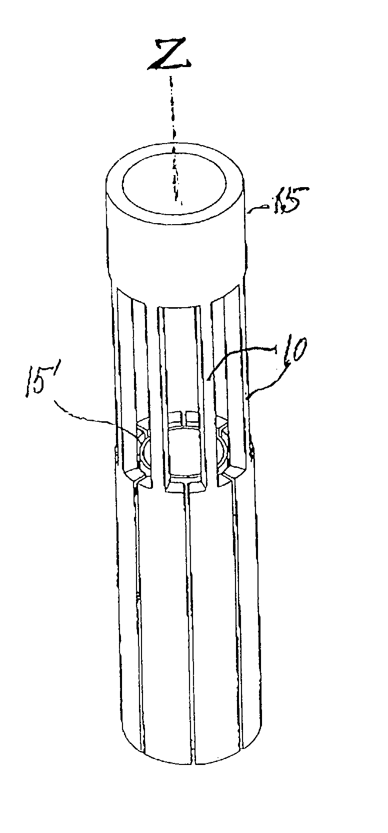
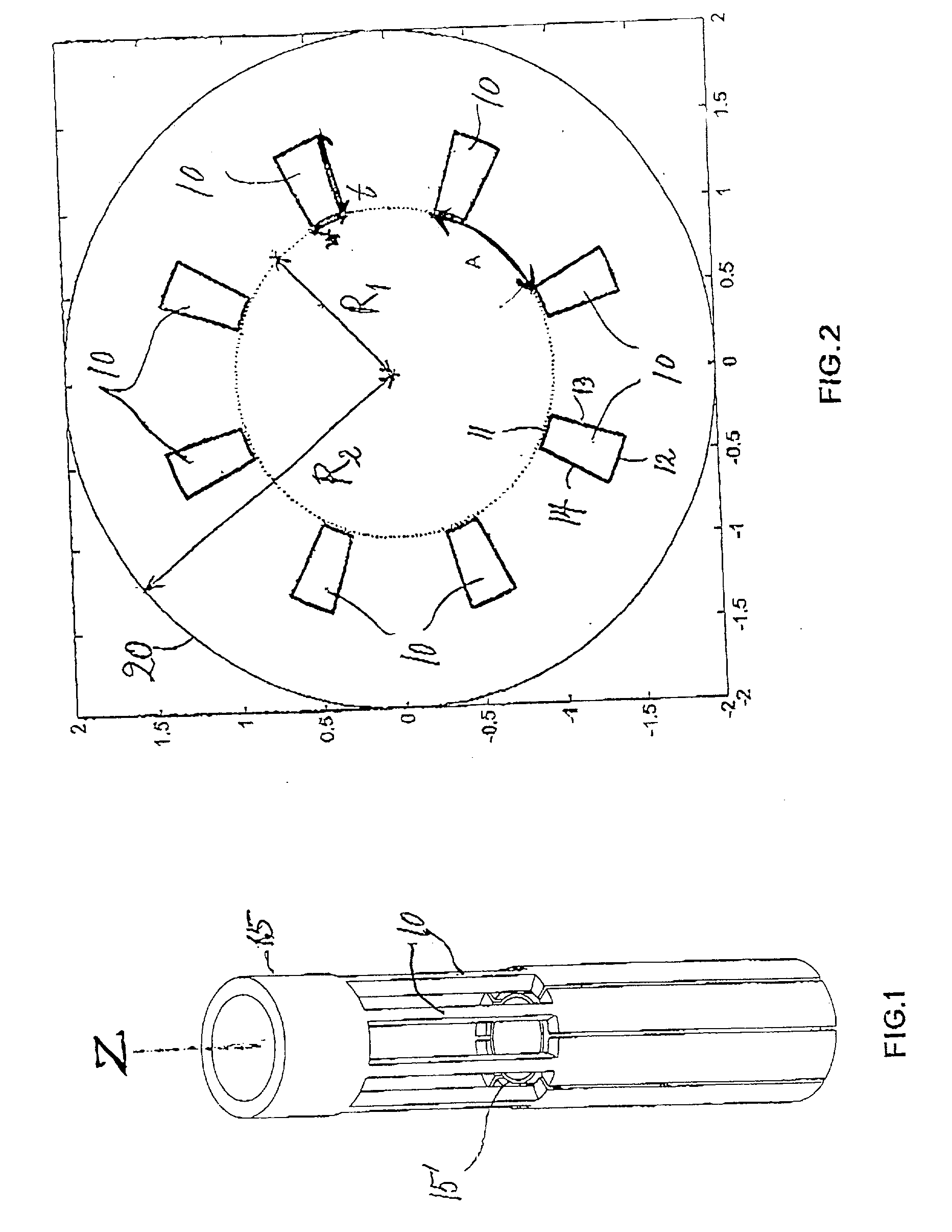
[0019] The invention is described next by way of a typical example of birdcage resonator coil geometry of a type having a plurality (N=8) of rungs. FIG. 1 is its external view, showing eight rungs 10 extending axially (in the z-direction) between two conductive rings 15 and 15' separated from each other along the z-direction. The width, thickness and general cross-sectional shape of the rungs 10 in this figure are meant to illustrate a feature of the invention. FIG. 2 is a sectional view of the resonator of FIG. 1 taken along the z-direction, showing the rungs 10 disposed circularly about the rings 15 at equal azimuthal intervals. In practice, the coil of FIG. 1 is disposed inside a radio frequency shield 20 (not shown in FIG. 1) with inner radius indicated by symbol R.sub.2. Each rung 10 has an internally facing surface 11, an externally facing surface 12 and two side surfaces 13 and 14 such that its cross-sectional shape as shown in FIG. 1 is a geometrical figure surrounded by two...


PUM


Abstract

A birdcage resonator has a pair of conductor rings separated from each other along a central axis and a plural number of axially disposed conductor rungs, which extend between the rings and are evenly spaced around the central axis. Each of the rungs has a sectional shape with thickness or a radial extension comparable to or greater than its width or its azimuthal extension. Measures of the width and thickness of the rungs may be determined by using them as parameters to calculate the values of Q factor from an analytical procedure to locate parameter value ranges corresponding to maximal Q. Geometric calculations for filling factor yield ranges of parameters providing for compromise parameter values. Saddle coils have been found to exhibit similar enhancement of Q with radially oriented conductor cross section.

Description

BACKGROUND OF THE INVENTION[0001] This invention relates to NMR resonators. More particularly, this invention relates to a method of optimizing birdcage and related resonators for high Q factor, as well as birdcage resonators thus optimized.[0002] It has been known to structure a radio-frequency resonator coil in a birdcage form in order to obtain a highly homogeneous magnetic field as described, for example, in U.S. Pat. No. 4,694,255 issued Sep. 15, 1987 to C. Hayes and "Experimental Design and Fabrication of Birdcage Resonators for Magnetic Resonance Imaging" (T. Vullo, et al., Magnetic Resonance in Medicine, 24, 243 (1992)). Birdcage resonators are so called because of their general structure having a pair of generally circular conductive elements (the "rings") separated in a longitudinal direction to define the axis of the resonator and a plurality of conductive segments (the "rungs") evenly spaced about the circumference of and interconnecting these two ring elements. The nome...

Claims


Application Information

Patent Timeline
Patent Type & Authority Applications(United States)
IPC IPC(8): G01R33/34
CPCG01R33/34046
Inventor DE SWIET, THOMASWONG, WAI HAROMO, MARCOFINNIGAN, JAMESBURNS, SEAN
Owner AGILENT TECH INC
Why Eureka
Try Eureka