Enhanced Subtitle D design standard composite liner

a technology of composite liner and subtitle, which is applied in the field of waste management, can solve the problems of low level of environmental protection assumed, inability to achieve direct and uniform contact" between liner components, and inability to meet the requirements of design standard composite liner, etc., and achieves the effect of reducing the tensile stress buildup in the fml component, avoiding potential shear strength concerns, and avoiding environmental pollution

Inactive Publication Date: 2003-10-23
CHANDLER PIERCE L JR
View PDF3 Cites 7 Cited by
  • Summary
  • Abstract
  • Description
  • Claims
  • Application Information

AI Technical Summary

Benefits of technology

0060] 9) Due to the overlapping, non-welded seams, tensile stress buildup in the FML component is minimized.
0061] 10)Potential shear strengt...

Problems solved by technology

This delay is usually the result of seam-welding logistics and the consideration of economy of scale.
The level of environmental protection assumed (in the Subtitle D rules) for the design standard composite liner is not being achieved in that "direct and uniform contact" between liner components is rarely, if ever, being achieved.
1) delay in FML component placement which allows degradation, deterioration, and damage to the compacted soil liner component.
2) wrinkling of the FML component when installed over large areas.
3) damage to the FML component from the seam welding and subsequent destructive testing.
As a result of the normal installation practice, almost all synergy between components is lost and leakage through the liner is controlled by defects in individual components.
Catastrophic increases in leakage through the FML component can occur as a result of conventional practice and/or FML properties.
1) stress cracking of embedded wrinkles in the FML;
2) tearing of the FML due to unrelieved tensile stresses;
3) destructive...

Method used


Image

  • Enhanced Subtitle D design standard composite liner
  • Enhanced Subtitle D design standard composite liner

Examples


Embodiment Construction

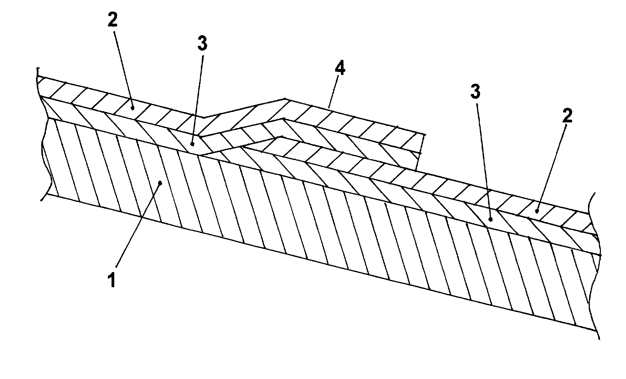
[0042] FIG. 1 shows the preferred embodiment. With reference to FIG. 1, a compacted soil liner component (1) is initially constructed on the subgrade. The compacted soil liner is constructed to a minimum thickness of two feet using materials and techniques necessary to attain a hydraulic conductivity of no more than 1.times.10.sup.-7 centimeters per second.

[0043] A flexible membrane liner (FML) component (2) with an intermediate bentonite layer component (3) bonded to the underside is placed over the entire constructed soil liner component (1). The FML / bentonite sheets or panels are successively placed with overlapping seams (4) "shingled" in the downslope direction.

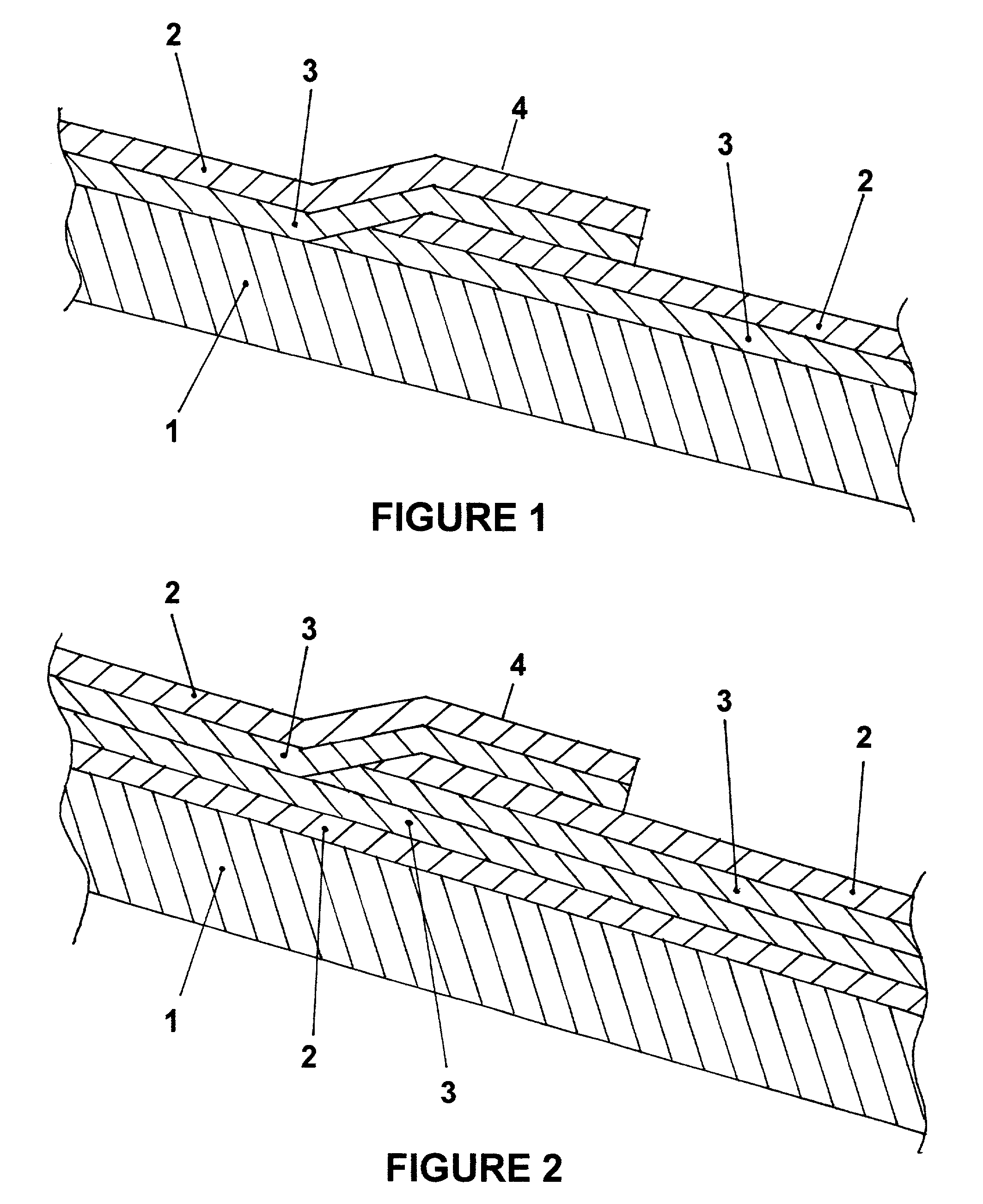
[0044] FIG. 2 shows an additional embodiment wherein an additional FML component (2) with bonded bentonite (3) is used. In this embodiment, the additional FML (2) is placed on the constructed soil liner component (1) with the bentonite layer component (3) side up. An FML component (2) with a bentonite layer component (3)...


PUM


Abstract

An enhanced composite liner system to be employed under waste management units and comprised of an upper flexible membrane liner component (2), an intermediate bentonite layer component (3), and a lower compacted soil liner component (1). The bentonite layer component (3) is bonded to the flexible membrane liner component (2). The flexible membrane liner component (2) utilizes overlapping seams (4) sealed by the bentonite layer component (3) to join the sheets or panels of the flexible membrane liner. The overlapping seams (4) are arranged shingle fashion in the downslope direction of the liner surface. The use of the bentonite layer component enhances direct and uniform contact between the flexible membrane liner component (2) and the underlying compacted soil liner component (1).

Description

[0001] Not applicable[0002] Field of Invention[0003] This invention relates to waste management and particularly to an improved method for waste-containment liner systems to be employed under land-based waste management facilities.FEDERALLY SPONSORED RESEARCH AND DEVELOPMENT[0004] This invention was not, in any way, developed as part of federally-funded or federally-sponsored research and development.[0005] Description of Prior Art[0006] Waste management and disposal practice was codified in response to the 1976 Resource Conservation and Recovery Act (RCRA) and the 1984 Hazardous and Solid Waste Amendments (HSWA) to RCRA. In 1991, U.S. EPA promulgated rules for non-hazardous waste management (primarily municipal solid waste) commonly referred to as "Subtitle D" rules to distinguish from Subtitle C or hazardous waste management rules. (Oct. 9, 1991 Federal Register, Volume 56, Number 196). These Subtitle D rules can be found in 40 CFR Parts 257 and 258.[0007] Subtitle D, 40 CFR Part ...

Claims


Application Information

Patent Timeline
IPC IPC(8): B09B1/00E02D31/00
CPCB09B1/00E02D31/004B09B1/004Y02W30/30
Inventor CHANDLER, PIERCE L. JR.
Owner CHANDLER PIERCE L JR
Why Eureka
Try Eureka