
Implantable textile prostheses having PTFE cold drawn yarns

a technology of textile prosthesis and cold drawn yarn, which is applied in the direction of prosthesis, blood vessels, weaving, etc., can solve the problems of loss of structural integrity, graft failure, and the use of yarns in these types of textile constructions

Inactive Publication Date: 2003-10-30
LIFESHIELD SCI
View PDF44 Cites 78 Cited by
  • Summary
  • Abstract
  • Description
  • Claims
  • Application Information

AI Technical Summary

Problems solved by technology

Typically, the yarns used in these types of textile constructions are subjected to strenuous conditions, such as constant rubbing against a stent during pulsation of blood.
Such abrasive forces can result in weakening of conventional textile prosthesis made with polyethylene terephthalate (PET) yarns, which can result in loss of structural integrity, and in extreme cases graft failure.
Use of PTFE yarns for textile vascular prostheses has been limited because finished PTFE yarns suitable for use in medical devices are often not commercially available to medical device manufacturers.
Unfinished PTFE yarns that are available, however, typically do not possess the physical characteristics necessary for such medical device uses, such as sufficient orientation, i.e. molecular alignment of the fibers, and the requisite uniform linear density.
This creates problems when processing such yarns into a textile prosthesis.
For instance, unfinished yarns may accumulate in the machine during the textile prosthesis manufacturing process or stretch to create a non-uniform prosthesis.
Additionally, problems may occur when such prostheses having unfinished PTFE yarns therein are placed in a body lumen because such yarns may unexpectedly and undesirably stretch.
Thus, the prostheses will not perform in a consistent and predictable manner.
As such, these yarns are not suitable for use in medical devices without further processing.
However, it may be difficult to control and maintain the elevated temperature that is necessary for heat drawing and it may be expensive to obtain heat drawing equipment.
Thus, conventional methods for drawing yarns suitable for use in implantable textile prostheses are less than satisfactory.
Such movement may cause abrasion of the graft by the metal stent, leading to a weakening of the integrity of the prosthesis.
This scissoring or shearing action is detrimental to the body's healing process.
A draw ratio of higher than 1.50 may result in breakage of the yarn.

Method used


Image

  • Implantable textile prostheses having PTFE cold drawn yarns
  • Implantable textile prostheses having PTFE cold drawn yarns
  • Implantable textile prostheses having PTFE cold drawn yarns

Examples


example 2

Woven Construction

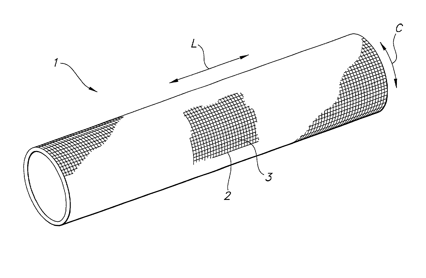
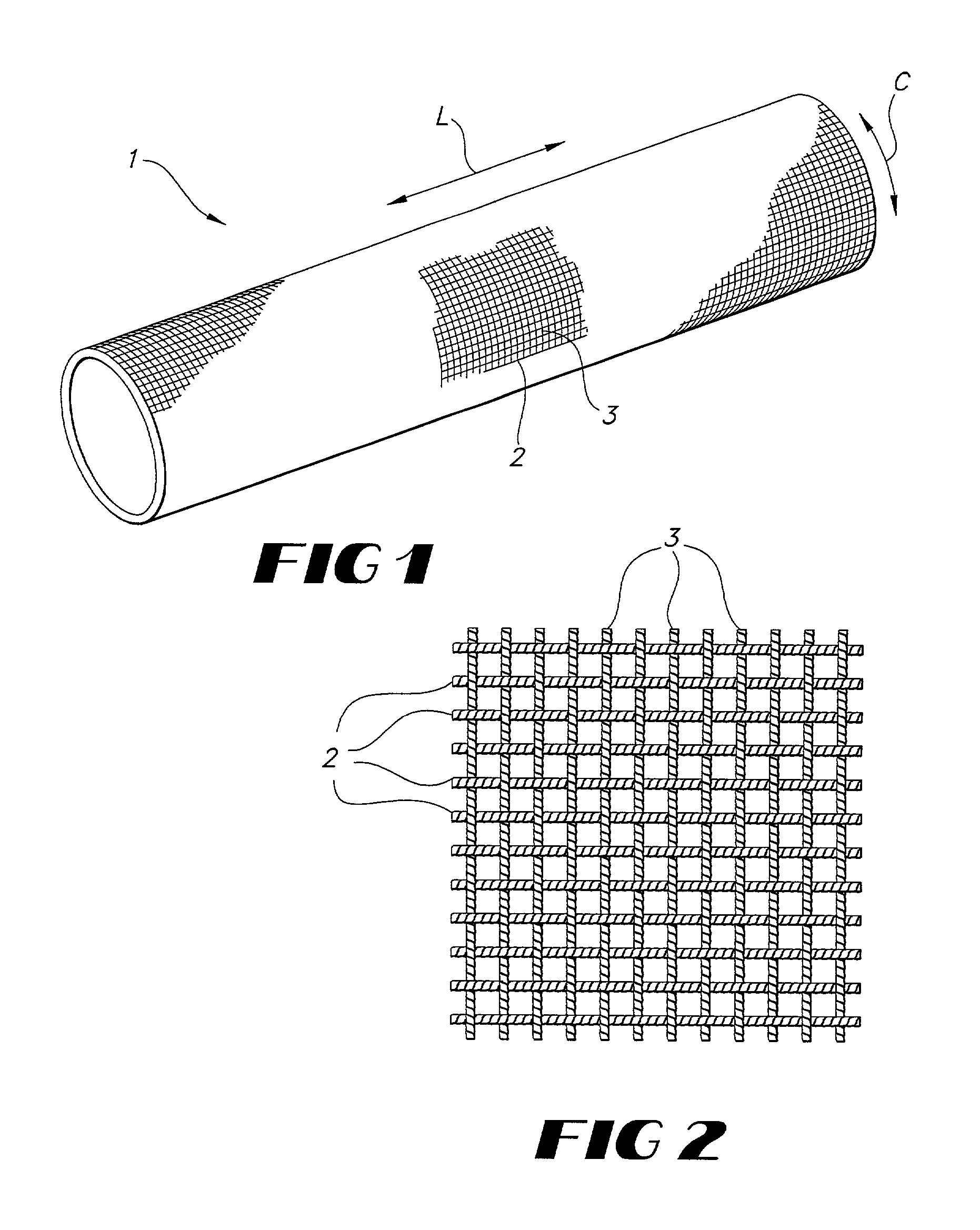
[0053] A graft-stent composite, in accordance with the present invention, is formed from a plain weave tubular fabric having a warp yarn of 225 denier, 30 filament cold drawn PTFE yarn and weft yarn of 225 denier, 30 filament cold drawn PTFE yarn. The ends per square inch are 188 per layer while the picks per inch are 88 per layer. The fabric so formed has a wall thickness of approximately 0.12 mm or less.

[0054] After weaving into a tubular prosthesis, the prosthesis is cut to a desired length, desirably with a laser to cut and fuse the ends simultaneously. The prosthesis is cleaned with sodium dodecyl sulfate and then rinsed with deionized water. The prosthesis is placed over a mandrel and heat set to precisely set the diameter and to remove any creases or wrinkles.

[0055] The prosthesis is optionally be crimped to impart longitudinal compliance and radial support. Crimp patterns shown in FIG. 6 includes a series of wave-like crimps therealong. Crimps may be impart...

example 3

Braided Construction

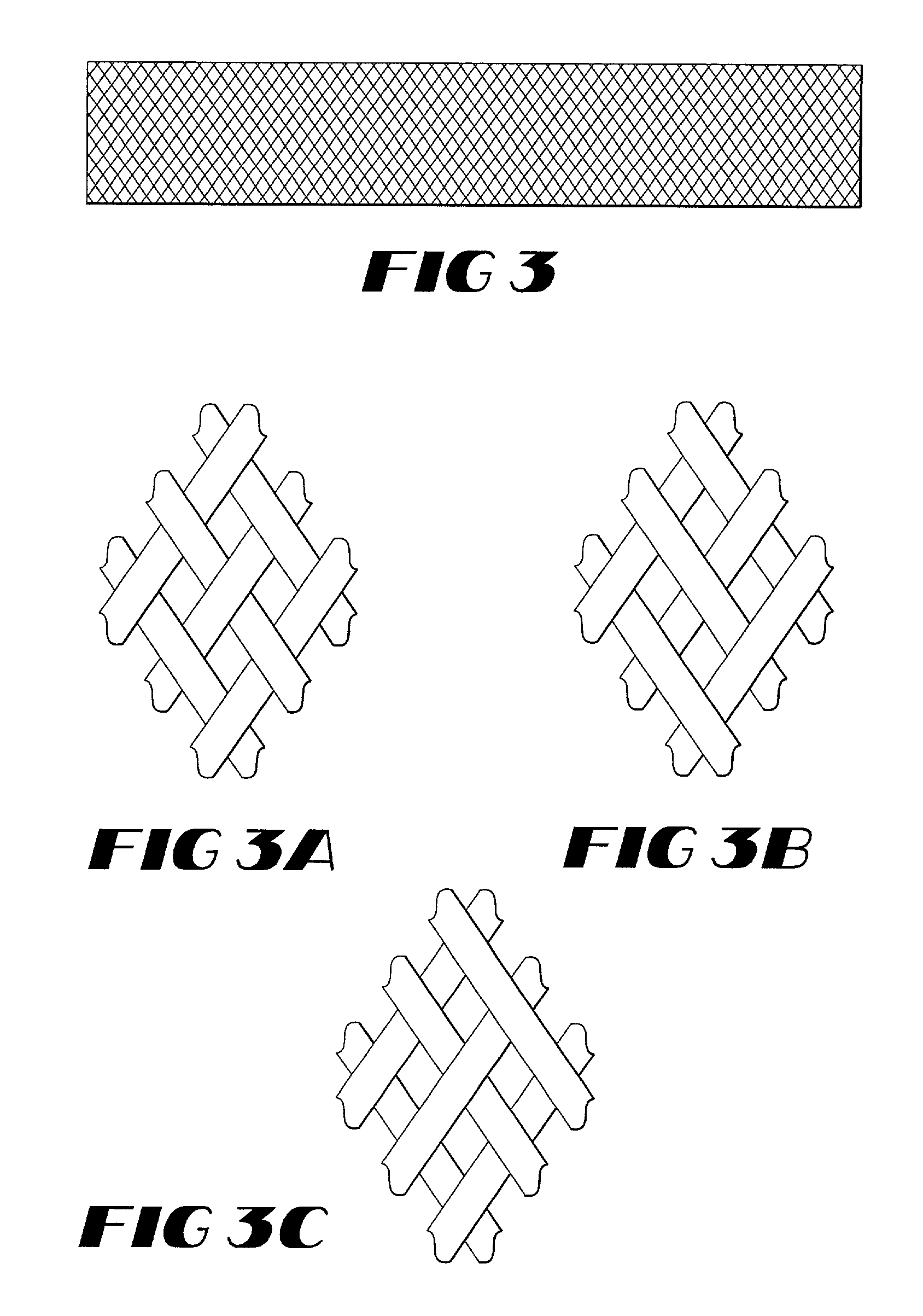
[0057] A regular twill braid is used to produce a tubular prosthesis. The warp yarns and fill yarns are constructed of a 225 denier, 30 filament cold drawn PTFE yarns. A prosthesis is braided using 192 bobbins and a 55 degree helix angle.

[0058] After braiding into a tubular prosthesis, the prosthesis is cut to a desired length, desirably with a laser to cut and fuse the ends simultaneously. The prosthesis is cleaned with sodium dodecyl sulfate and then rinsed with deionized water. The prosthesis is placed over a mandrel and heat set to precisely set the diameter and to remove any creases or wrinkles.

example 4

Interlocked 3-D Braided Construction

[0059] A tubular prosthesis is formed from an interlocked three-dimensional, multi-layered braided structure, as shown in FIG. 7. The prosthesis is preferably braided on a mandrel at a braid angle of 54.5 degrees. The prosthesis includes four interlocked layers made 225 denier, 30 filament cold drawn PTFE yarns having 192 bobbins (bobbins refer to the number of carriers within the braiding machine).

[0060] After braiding into a tubular prosthesis, the prosthesis is cut to a desired length, desirably with a laser to cut and fuse the ends simultaneously. The prosthesis is cleaned with sodium dodecyl sulfate and then rinsed with deionized water. The prosthesis is placed over a mandrel and heat set to precisely set the diameter and to remove any creases or wrinkles.


PUM

PropertyMeasurementUnit
Linear densityaaaaaaaaaa
Temperatureaaaaaaaaaa

Abstract

The present invention provides an implantable prosthesis and more specifically, an implantable tubular textile prosthesis comprising a biocompatible fabric having inner and outer surfaces and first and second ends; the fabric having a textile construction comprising cold drawn PTFE yarns having a substantially uniform denier and high molecular orientation. Use of cold drawn PTFE yarns result in implantable prostheses that have excellent abrasion resistance, strength and lubricity properties. Useful textile constructions include weaves, knits, braids, filament windings, spun windings and combinations thereof. The prostheses of the present invention are lubricious and have characteristics that closely resemble the properties of a natural body lumen.

Description

[0001] The present invention relates to an implantable textile prosthesis. More particularly, the present invention relates to an implantable textile prosthesis with substantially improved lubricious properties having cold drawn polytetrafluoroethylene (PTFE) yarns therein.BACKGROUND OF RELATED TECHNOLOGY[0002] Vascular grafts are commonly used as soft tissue prostheses to replace or repair damaged or diseased veins and arteries. Conventional textile implantable prostheses are manufactured using yarns made of biocompatible and biostable material. To maximize the effectiveness of prostheses, it is desirable that the prostheses have characteristics that closely resemble that of the natural body lumen. In particular, prostheses desirably exhibit long term wear and kink resistance. Typically, the yarns used in these types of textile constructions are subjected to strenuous conditions, such as constant rubbing against a stent during pulsation of blood. Such abrasive forces can result in ...

Claims


Application Information

Patent Timeline
IPC IPC(8): A61F2/00A61L27/00A61F2/06A61L27/16A61L27/34A61L27/50A61L31/04A61L31/10
CPCA61F2/0063A61F2/06A61L27/16A61L27/34A61L27/507A61L31/04A61L31/10C08L27/18
Inventor EDENS, WESLEY I.HEBERT, CHARLES B.
Owner LIFESHIELD SCI
Learn More