Starter for a motor vehicle

a technology for starting devices and motor vehicles, applied in the direction of engine starting devices, muscle operated starters, machines/engines, etc., can solve the problems of difficult sizing of solenoid components, difficult kinematics optimization, and large development time, so as to reduce the power of electromagnetic contactors and their radial size, not to increase the effect of axial siz

Inactive Publication Date: 2004-02-05
VALEO EQUIP ELECTRIC MOTEUR
View PDF20 Cites 35 Cited by
  • Summary
  • Abstract
  • Description
  • Claims
  • Application Information

AI Technical Summary

Benefits of technology

0036] Thus, by virtue of the rotational locking of the starter head and these means, it is possible to reduce the power of the electromagnetic contactor and its radial size still further, by virt

Problems solved by technology

The kinematics is difficult to optimise given the large number of parameters influencing it.
Sizing the solenoid is therefore not easy and takes a large amount of development time.
It is also necessary to adapt the solenoid to the starter heads which it must set in movement, which results in a lack of standardisation.
in the tooth against tooth position, the electric motor is powered before the pinion 1 of the starter head has penetrated the ring C. If the surface finishes of the starting ring C of the thermal engine or of the pinion 1 are degraded, if the stiffness of the tooth against tooth spring is too lo

Method used


Image

  • Starter for a motor vehicle
  • Starter for a motor vehicle
  • Starter for a motor vehicle

Examples


first embodiment

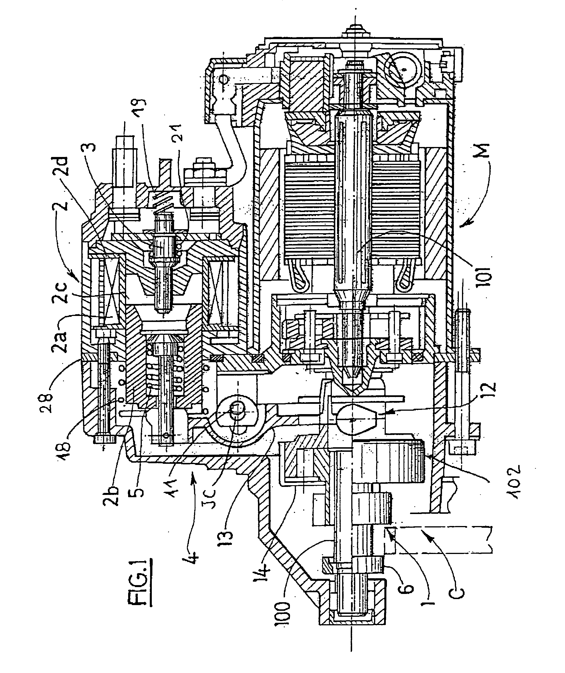
[0106] as depicted in FIGS. 3 and 4, the locking in rotation is effected by a fork 13 preferably produced from rigid material. A device for locking in rotation therefore acts between the starter head and the fork.

[0107] Thus according to the invention the starter head is locked in rotation by means of cooperation between the fork 13 and the driver 12 for its passage from its idle position (FIGS. 3 and 4) to its position of meshing via its pinion, with the starting ring.

[0108] These cooperation means, which in FIGS. 3 and 4 are means of locking in rotation with cooperation of shapes, are located at the fingers situated at the base of the fork 13 and at the rear face of the driver 12. More precisely, the branches or arms of the fork are received in a groove in the driver 12 delimited by the flanks 121, 122, respectively front and rear, transverse with respect to the axis of the shaft 101.

[0109] In the idle state the fingers of the fork 13 are in abutment on the smooth rear flank 122 ...

second embodiment

[0146] In a second embodiment visible in FIG. 34, only one plate P0 is used as well as a single pair of contacts C5 and C6 which are offset axially with respect to each other along the axis of the relay. The contact C5 provides the pre-rotation of the electric motor M and the contact C6 supplies this same motor at full power. The contact C6 is connected to the battery. In one example embodiment, the pre-rotation resistive coil 39 is connected to C6 by means of an electrical connection 48, for example of the wire type. Advantageously, the contact C5 is connected directly to the electric motor by an electrical connection means 49. This embodiment has the advantage of not using external connection terminals and an external connection wire. This avoids problems of watertightness at the external terminals and also helps to reduce the size of the starter and its cost and weight.

[0147] The contact plate in a first phase is perpendicular to the movable core and moves in contact with a conta...

third embodiment

[0156] In a third embodiment visible in FIGS. 35 and 36, a contact plate P3 is mounted on a movable shaft 40 fixed to the movable core and comprising at its external periphery helical flutes 50 cooperating with complementary helical flutes produced at the internal periphery of the plate P3. The shaft 40 carries in radial projection a stop 53 for the plate P3.

[0157] At rest, the contact plate P3 is kept pressed against a shoulder 54 on the body of the solenoid 2a by an elastic washer 52 fixed to the movable shaft 40. The plate P3 has a special shape, as can be seen in FIG. 36. It comprises two circular sectors, one of which, with a greater circumferential extent, is intended to cooperate with the contact C7 and the other with the contact C8 or C9, axially of the same height. The contacts C7 and C9 are diametrically opposed.

[0158] When the movable core moves forward, the plate, driven by the movable shaft and held by the stop 33, follows the translation movement towards the rear. It c...


PUM


Abstract

The starter for a motor vehicle comprises a starter head provided with a driver (12) and a pinion (1), an electric motor (M) provided with a shaft (101) able to drive a starter-head shaft (100), an electromagnetic contactor (2) extending parallel to the electric motor (M) above it and comprising a movable core (2d), a fork (13) mounted with articulation at its top end on the movable core (2b); the driver (12) comprises a groove for receiving the bottom end of the fork (13) delimited by two flanks (121, 122) whilst the starter head is locked in rotation by means of cooperation between the fork (13) and the driver (12) for its passage from its idle position to its position of meshing with the starting ring.

Description

[0001] The present invention concerns starters for motor vehicles.PRIOR ART[0002] Such a starter is depicted in FIG. 1 and comprises an electric motor M mounted inside a first metallic casing, an electromagnetic contactor 2 extending parallel to the electric motor M and comprising a winding 2a mounted inside a second metallic casing. The two casings are fixed, here by means of tie rods, to a support 4 with the interposing here of a support plate 28 of an epicyclic gearbox. The support 4 is a cast part based on aluminium which is intended to be fixed to the crankcase of the internal combustion engine of the motor vehicle, hereinafter referred to as the thermal engine. The support 4 provides the earth return and comprises a front end in the shape of an ogive open locally for the passage of the starting ring C of the vehicle thermal engine. This ogive is connected to an area for fixing and centring respectively the electric motor M, the contactor 2 and the support 2 on the thermal engi...

Claims


Application Information

Patent Timeline
IPC IPC(8): F02N15/06H01H51/06
CPCF02N15/023Y10T74/132H01H51/065F02N15/067F02N15/06
Inventor VILOU, GERARDBOCQUET, CHANTALCHANE-WAYE, OLIVIERJACQUIN, PASCAL
Owner VALEO EQUIP ELECTRIC MOTEUR
Why Eureka
Try Eureka