Power system having generator driven by engine
a technology of power system and generator, which is applied in the direction of electric generator control, electric motor propulsion transmission, locomotive transmission, etc., can solve the problems of enlarging the capacity of the inverter circuit, reducing the efficiency of power generation, and preserving the compactness of the system, so as to achieve the effect of increasing the capacity without spoiling the compactness
- Summary
- Abstract
- Description
- Claims
- Application Information
AI Technical Summary
Benefits of technology
Problems solved by technology
Method used
Image
Examples
embodiment 1
[0043] (Embodiment 1)
[0044] An apparatus for controlling the operation of power conditioners according to the invention is provided for power conditioners having a generation system generating electric power in association with an external electric power system such as a commercial electric power system. The power conditioners are interconnected to the external electric power system, and mutually interconnected through information exchanging means. At least one of the power conditioners monitors the reverse power flow. The power conditioners exchange the monitor information with information of the other power conditioners. Accordingly, outputs of all of the power conditioners are equalized.
[0045] Each of the power conditioners is provided with a transmitter-and-receiver and a communication medium which serve as the information exchanging means. The transmitter-and-receiver is connected through the communication medium to the transmitter-and-receiver of another power conditioner. As ...
example 1-1
(EXAMPLE 1-1)
[0066] Hereinafter, description will be given on an example of the invention according to drawings.
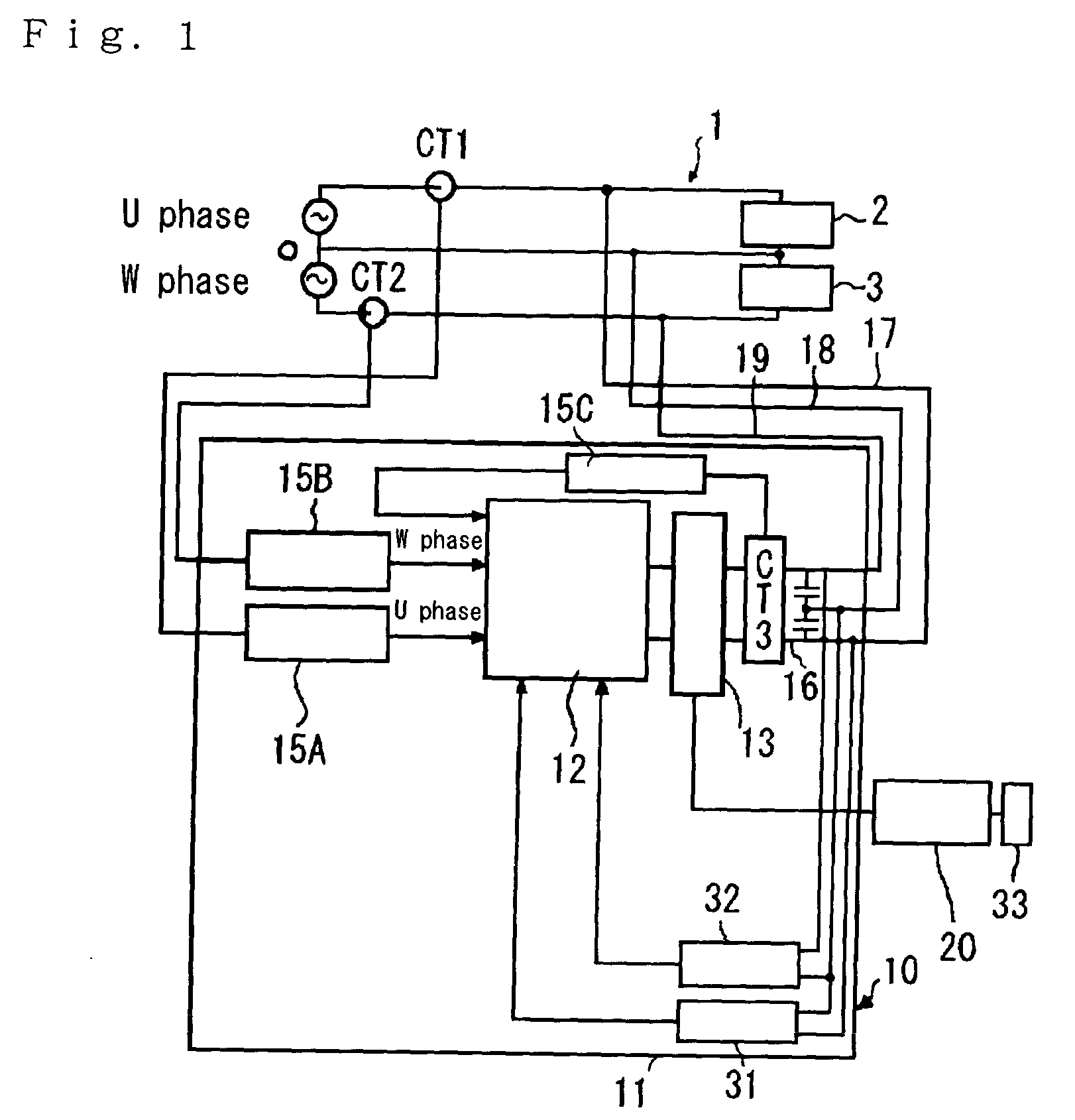
[0067] As shown in FIG. 1, an interconnection system having a power conditioner 10, which associates electric power generated by an electric power generation system 20 with an external electric power system 1 such as a commercial electric power system, controls for restricting output electric power of the power conditioner 10 when the reverse power flow is detected.
[0068] The power conditioner 10 comprises an inverter circuit 13 for converting electric power from the electric power generation system 20 into alternating-current power synchronized with the power from the external electric power source; respective CT input circuits 15A and 15B for U phase line and W phase line for inputting detected signals from respective current detectors (AD converters) CT1 and CT2 for detecting direction and amount of respective current flowing in U phase line and W phase line of the exte...
embodiment 1-1
[0076] (Embodiment 1-1)
[0077] An embodiment 1-1 according to the invention is shown in FIGS. 3 to 9.
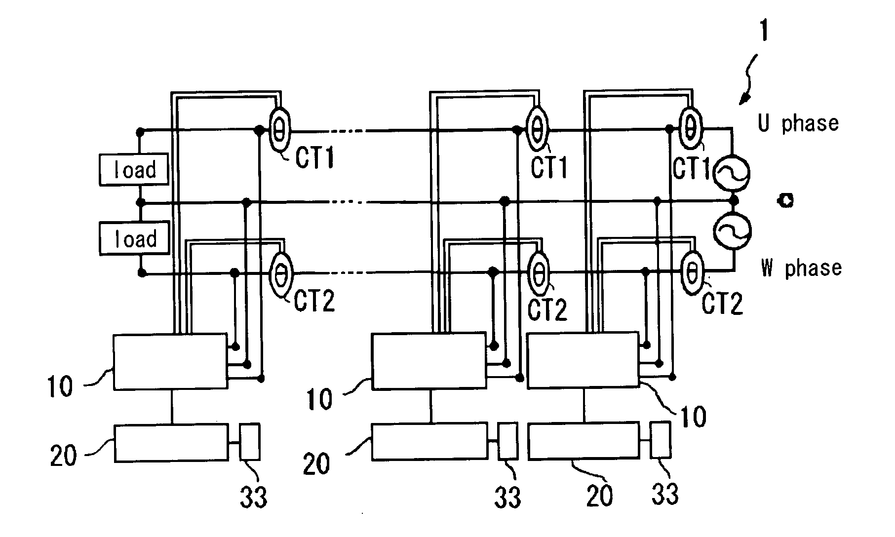
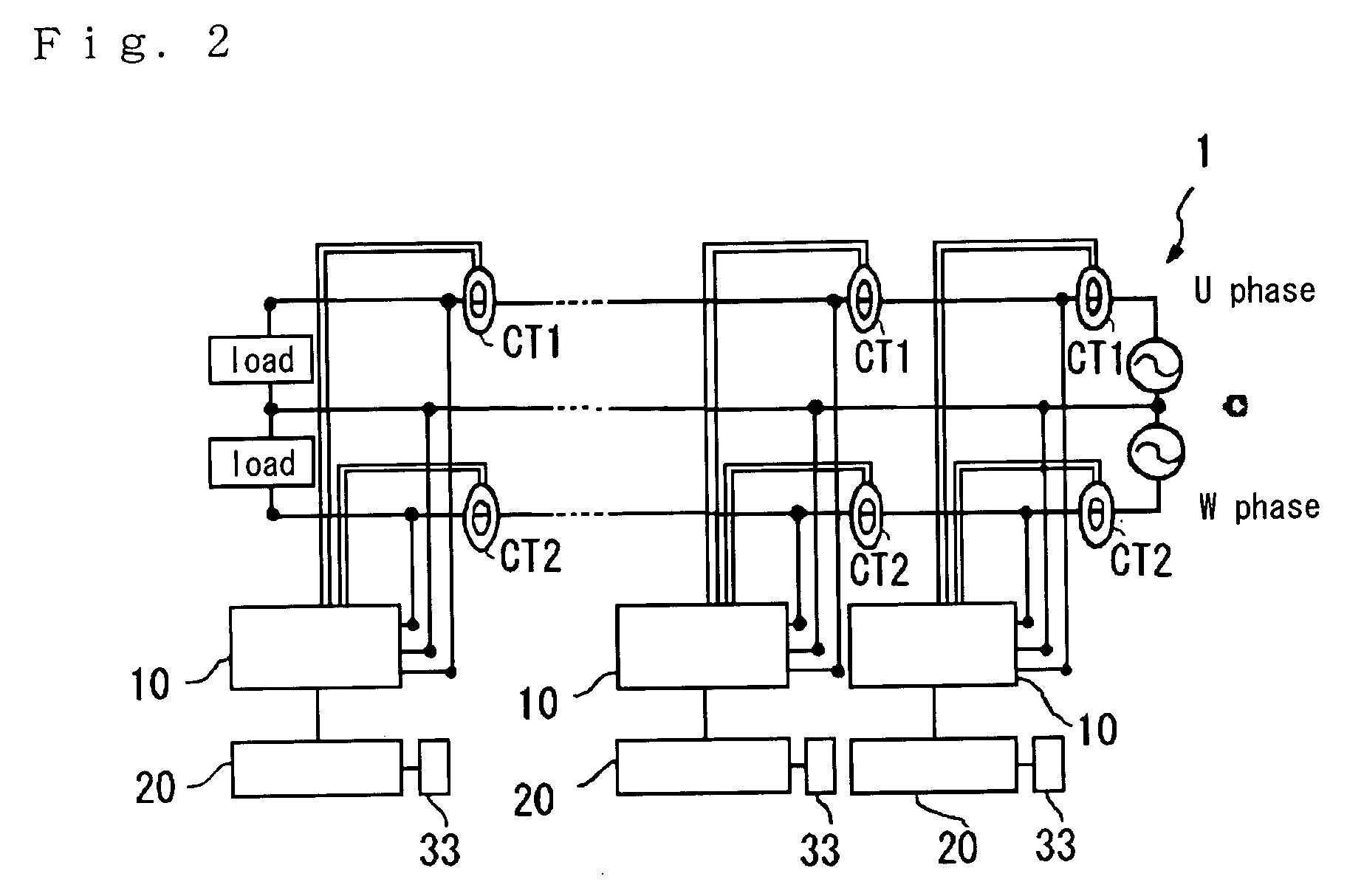
[0078] FIG. 3 illustrates an interconnection system which links multiple cogeneration systems A with the external electric power system 1. In FIG. 3, the external electric power system 1 has three lines for single-phase power. A first (one) load 2 is connected between U phase line and neutral line O of the external electric power system 1. A second (another) load 3 is connected between W phase line and neutral line O of the external electric power system 1.
[0079] Each of the cogeneration systems A has the power conditioner 10, the electric power generation system 20 for supplying electric power to the power conditioner 10, and the exhaust heat recovery device 33. In the power conditioners ranked in order away from the external electric power system 1, the first power conditioner is referred to as "10-1", the second as "10-2", and the power conditioner of an ordinal rank n is referred ...
PUM
 Abstract
Description
Claims
Application Information
 - R&D
- Intellectual Property
- Life Sciences
- Materials
- Tech Scout
- Unparalleled Data Quality
- Higher Quality Content
- 60% Fewer Hallucinations
Browse by: Latest US Patents, China's latest patents, Technical Efficacy Thesaurus, Application Domain, Technology Topic, Popular Technical Reports.
© 2025 PatSnap. All rights reserved.Legal|Privacy policy|Modern Slavery Act Transparency Statement|Sitemap|About US| Contact US: help@patsnap.com


