

Apparatus for evaporation of materials for coating of objects
a technology of evaporation apparatus and material, applied in the direction of ion implantation coating, chemical vapor deposition coating, coating, etc., can solve the problems of reducing the life of the cathode, affecting the physical and chemical properties of the coating, and affecting the wear of the electrode at the moment of irregular wear
- Summary
- Abstract
- Description
- Claims
- Application Information
AI Technical Summary
Benefits of technology
Problems solved by technology
Method used
Image

Examples
example 1
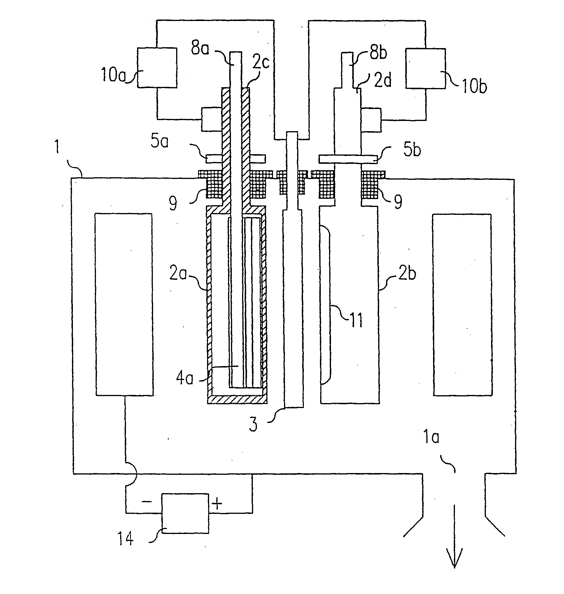
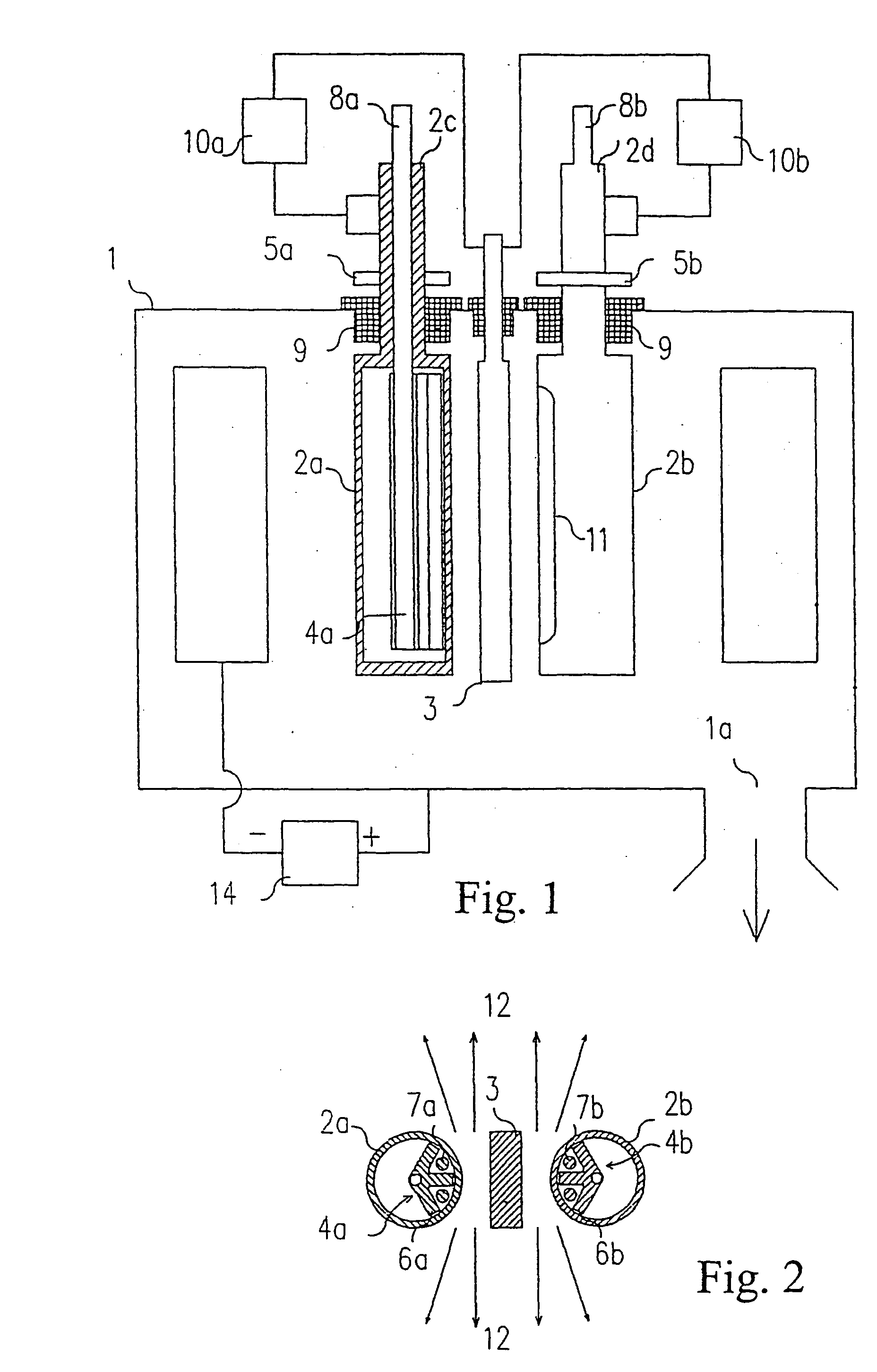
[0035] The centre of the coating chamber 1 (FIG. 1) accommodates an apparatus for evaporation of materials according to the invention that is referred to as evaporating device in the further description. The coating chamber 1 is provided by outlet 1a for gas evacuation. The basic parts of the evaporating device are cathodes 2a and 2b of the low voltage arc, anode 3 of the low voltage arc and source 4a and 4b of magnetic field (FIGS. 1 and 2). Cathodes 2a and 2b are cylindrical, i.e. they have cylindrical or similar form, they are hollow and at least their outer surface is made of material suitable for evaporation by the method of low voltage arc for coating by physical vapour deposition method, such as titanium or aluminium. Cathodes 2a and 2b pivot on their bearing parts 2c and 2d using not illustrated bearings. The bearing parts 2c and 2d of cathodes 2a and 2b are provided with pulleys 5a and 5b that are linked with a not illustrated driving mechanism. Cathodes 2a and 2b accommoda...
example 2
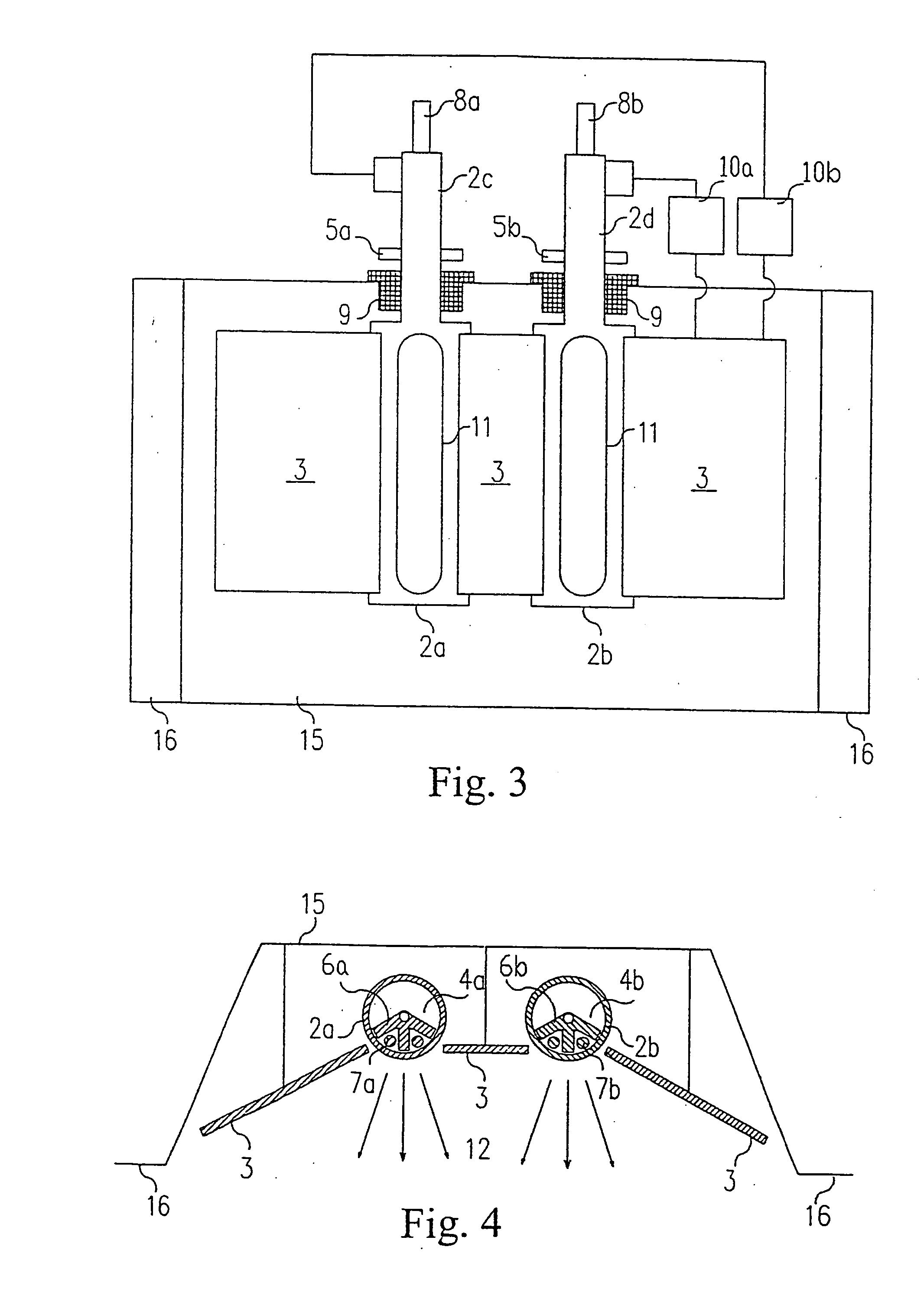
[0039] The not illustrated coating chamber is provided with door 15 attached to it over flange 16 (FIGS. 3 and 4). Door 15 is placed in the wall of a not illustrated coating chamber, being conductively connected with the latter and creating a closed space with it. The door 15 accommodates the evaporating device. The basic parts of the evaporating device are cathodes 2a and 2b of the low voltage arc, anode 3 of the low voltage arc and source 4a and 4b of magnetic field. Cathodes 2a and 2b pivot similarly as in example 1, their rotary motion being derived from pulleys 5a and 5b. Cathodes 2a and 2b accommodate, in their inside, the sources 4a and 4b of magnetic field that are created by pole shoes 6a and 6b and electromagnetic coils 7a and 7b. The pole shoes 6a and 6b are made of magnetically soft material, they are fixed by electromagnetic coils 7a and 7b and rigidly held by carriers 8a and 8b similarly as in example 1, so as to allow the pole shoes 6a and 6b to be directed to the cen...
example 3
[0042] Door 15 (FIGS. 5 and 6), which is placed similarly as in example 2 in the wall of a not illustrated coating chamber, with which it is conductively connected, accommodates an evaporating device. The basic parts of the evaporating device are cathode 2 of the low voltage arc, anode 3 of the low voltage arc and source 4 of magnetic field. Cathode 2 is cylindrical and immovable, however, it is arranged adjustably or shiftably in order to be either only turnable or turned and adjusted, e.g., by manual setting. The arrangement allows adjusting to three positions by 120.degree. increments. Anode 3 is immovable.
[0043] Cathode 2 accommodates in its inside the source 4 of magnetic field created by pole shoe 6 made of magnetically soft material and an electromagnetic coil 7 firmly connected with it. This system, i.e. the whole source 4 of magnetic field, pivots inside cathode 2 or has the possibility to turn around the axis of cathode 2 by pulley 5 accommodated on carrier 8 that is turna...
PUM
| Property | Measurement | Unit |
|---|---|---|
| Magnetic field | aaaaa | aaaaa |
Abstract
Description
Claims
Application Information