Method and device for fluid treatment

a fluid treatment and fluid technology, applied in water/sewage treatment by degassing, water treatment parameter control, separation processes, etc., can solve the problems of odor components, long residence time of sludge, and worsening the working environment in concentration processes, so as to reduce the amount of injected flocculating agent, reduce the amount of odor, and reduce the effect of settling

Inactive Publication Date: 2004-04-22
EBARA CORP
View PDF3 Cites 22 Cited by
  • Summary
  • Abstract
  • Description
  • Claims
  • Application Information

AI Technical Summary

Benefits of technology

0052] A controller controls flow rates of the respective pumps in response to signals from flow meters in the supply pump, the floating and concentrated sludge discharge pump, the lower separated liquid discharge pump, and the like, and from level meters provided in the device, so that the water level in the vessel is always maintained at a predetermined level. Most gaseous components such as hydrogen sulfide or methyl mercaptan dissolved in the suspension liquid are removed under a decompressed atmosphere from the floating and concentrated sludge and the lower separated liquid which have been subject to the decompressing process in the vessel. Accordingly, odor is largely reduced, and odor components produced during the flocculating process in the subsequent flocculation reaction tank 4 or during the dewatering process in the dewatering device 7 are largely reduced.
0053] Although the floating and concentrated sludge which has been separated in the decompressing device 2 may be introduced directly into the flocculation reaction tank 4 and mixed and agitated with a polymer flocculating agent, the floating and concentrated sludge is delivered to the mixing tank 12 before being delivered to the flocculation reaction tank 4. Properties of the lower separated liquid separated in the decompression concentrating device 2 are different depending on the properties of the original suspension liquid. When the concentration of the suspension materials in the lower separated liquid is relatively low, the lower separated liquid is delivered as a concentrated separated liquid to a water treatment process. When the concentration of the suspension materials is relatively high, the lower separated liquid is concentrated by settling under gravity as a lower separated sludge in a conventional gravity concentration tank. Since the lower separated sludge has been subject to the decompressing process in the decompression concentrating device 2, it has considerably fewer fine bubbles which would inhibit the settling tendency, so that the suspension materials in the lower separated sludge have an extremely good settling tendency. The settled and concentrated sludge which has been concentrated in the gravity concentration tank is mixed in the mixing tank 12 with the floating and concentrated sludge, which has been separated in the decompression concentrating device 2, into

Problems solved by technology

Moreover, in a case of a suspension liquid in which a large amount of odor components is dissolved, odor components are produced in these concentration processes to worsen the working environment in the concentration processes.
In an intensive sludge treatment plant or the like which collectively treats sludge produced from a plurality of sewage treatment plants in a metropolitan area or the like, sludge transported through pipelines from the respective treatment plants (which is referred to as arrival sludge) has a long residence time, particularly in a closed space, and is intensively decayed in many cases.
Simultaneously, the flocculati

Method used


Image

  • Method and device for fluid treatment
  • Method and device for fluid treatment
  • Method and device for fluid treatment

Examples


Embodiment Construction

[0056] Examples of operational results of treatment plants according to Cases 1, 2, 3 of the present invention will be described below. The present invention is not limited to the following examples.

[0057] Treatment plants according to a conventional method and Cases 1, 2, 3 of the present invention are examples in which sludge produced in a plurality of sewage treatment plants is delivered through pipelines to a single sludge plant to collectively treat the sludge.

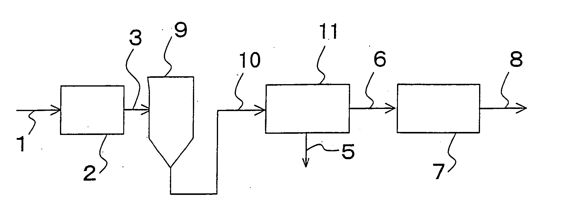
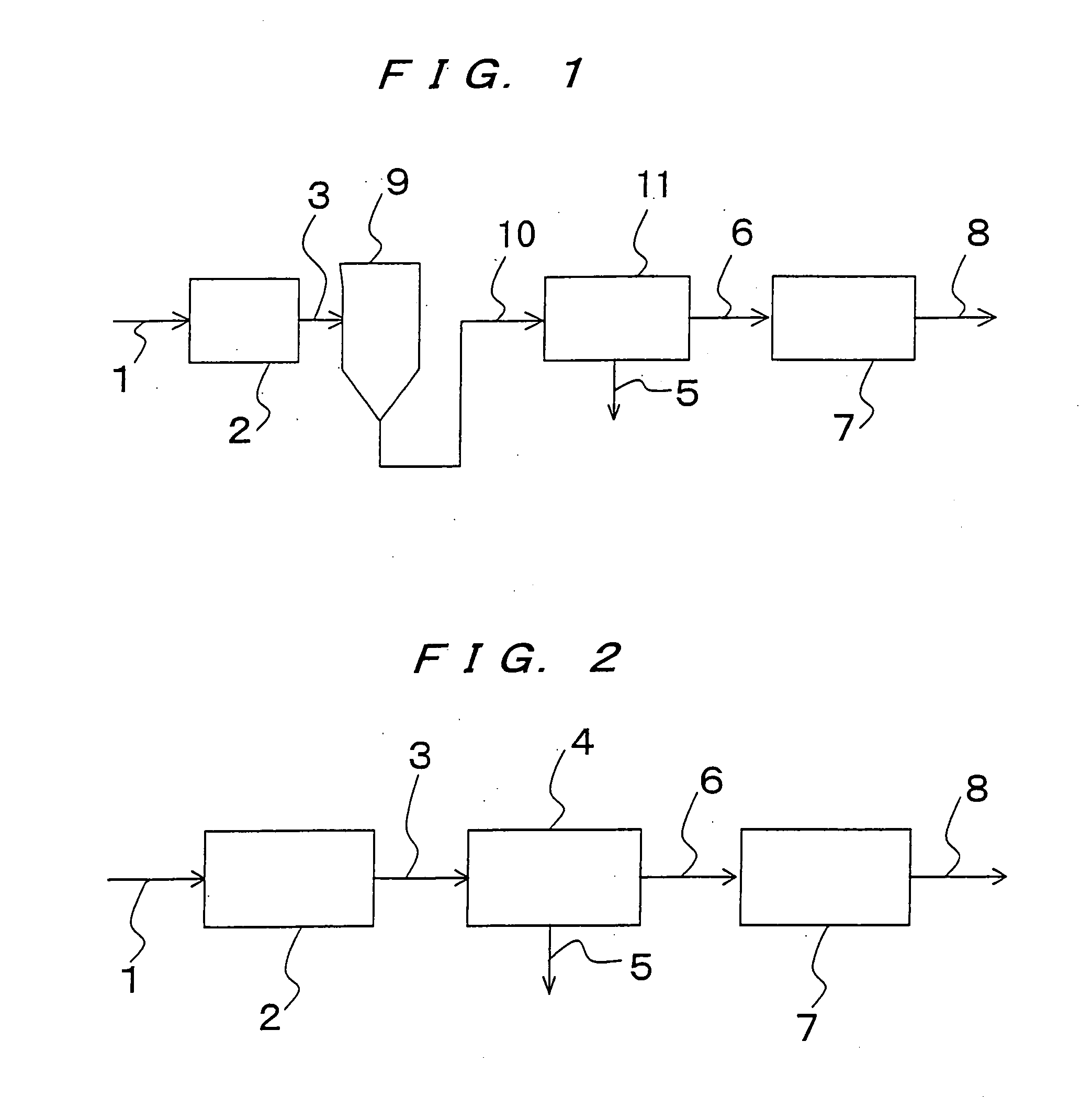
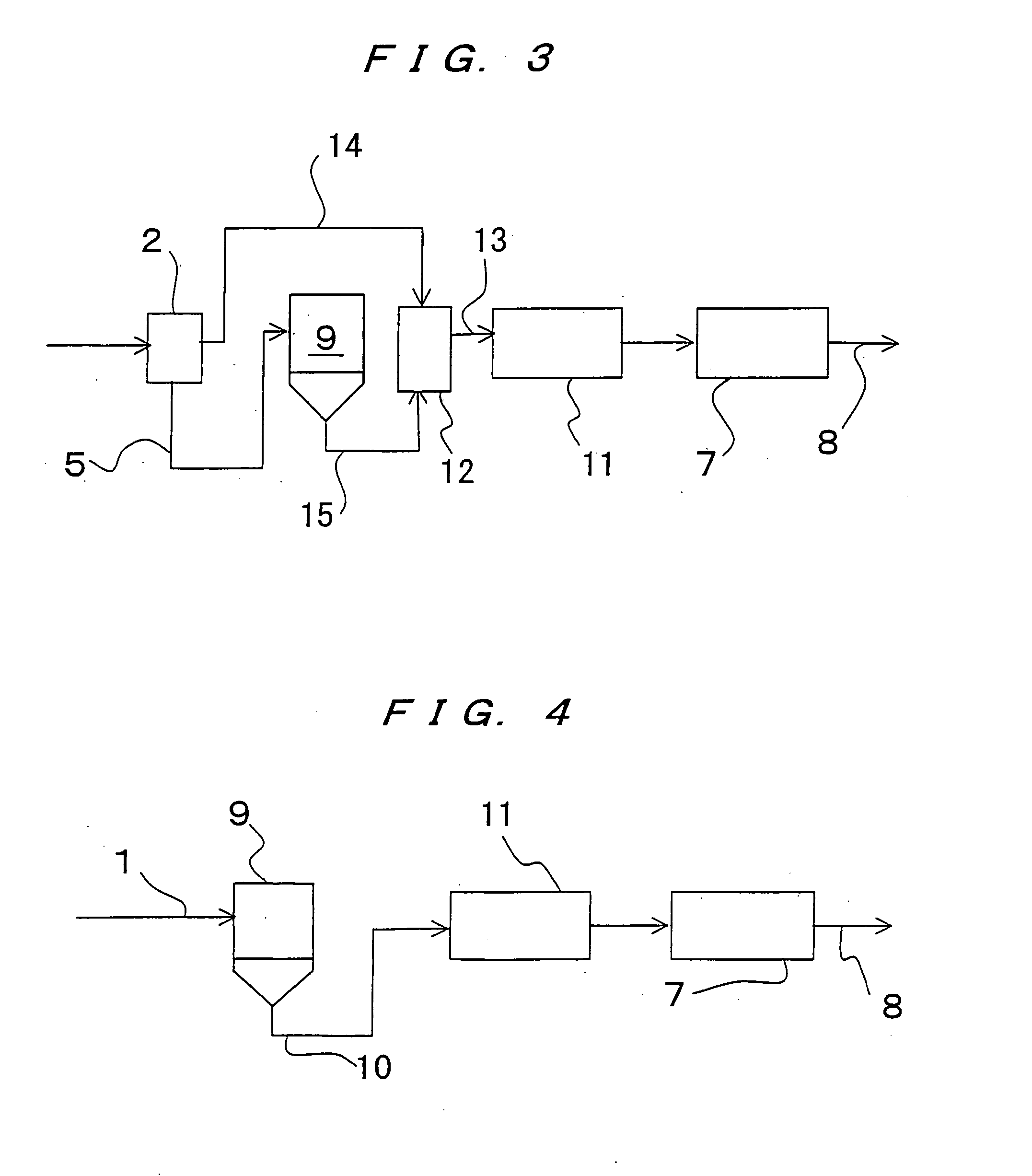
[0058] A conventional sludge treatment plant comprises a gravity concentration tank 9 for receiving sludge delivered through pipelines from a plurality of sewage treatment plants and concentrating the sludge under gravity to produce concentrated sludge 10, a flocculation reaction tank 11 for mixing a polymer flocculating agent and the concentrated sludge 10 from the gravity concentration tank 9 to produce flocculated floc 6 and discharging the flocculated floc, and a beltpress-type dewatering device 7 for dewatering the f...


PUM

PropertyMeasurementUnit
Pressureaaaaaaaaaa
Forceaaaaaaaaaa
Pressureaaaaaaaaaa

Abstract

The present invention relates to a technology which can efficiently concentrate a suspension liquid which needs to be concentrated in sewage treatment plants or various waste water treatment plants, particularly sludge or the like which contains a large amount of odor components which will adversely be decayed and is hard to concentrate. The present invention can prevent odor substances from being produced in a concentration process, and can remarkably reduce the amount of odor components, carbonic acid, and the like contained in concentrated sludge or a lower separated liquid. Specifically, in a process of concentrating or dewatering residual evaporated substances in a liquid, when sludge is held under a reduced pressure of 5 to 70 kPa for less than 15 minutes, a portion of gas components dissolved in the liquid is changed into gaseous phase, and activation of microorganisms in the liquid is restricted. After a decompressing process is performed under the reduced pressure, the liquid is introduced into a gravity concentration tank for gravity concentration, or the decompressed liquid or the gravity-concentrated sludge is introduced into a flocculation reaction tank for flocculation, and is then dewatered by a dewatering device.

Description

[0001] The present invention relates to a technology of separating a portion of a plurality of components contained in a liquid according to an intended use, and more particularly to a method and apparatus of treating a liquid in which floating suspension materials, oils, or the like are required to be concentrated in sewage treatment plants, various waste water treatment plants, or the like.[0002] More specifically, the present invention relates to a technology which employs a phenomenon in which a gas component is emitted from a suspension liquid into gaseous phase by introducing the liquid into a hermetically sealed vessel and holding the liquid under a reduced pressure, thereby improving gravity concentration, a flocculating tendency, and dewaterability of sludge after a decompression process and reducing the amount of odor produced. Further, the present invention relates to a sludge treatment technology which can dispense with a concentration process such as gravity concentrati...

Claims


Application Information

Patent Timeline
IPC IPC(8): C02F1/00C02F1/20C02F1/24C02F1/38C02F1/52C02F11/12
CPCC02F1/20C02F1/24C02F1/38C02F2303/02C02F11/12C02F2001/007C02F2301/063C02F1/52C02F11/121C02F11/147C02F1/5209C02F11/14C02F2201/002C02F2209/03
Inventor HAGINO, TAKAOHATA, RYOSUKEIRIUCHIJIMA, YOSHIHARUYOSHIDA, HIDEKI
Owner EBARA CORP
Why Eureka
Try Eureka