Membrane pressure sensor containing silicon carbide and method of manufacture

a technology of membrane pressure sensor and silicon carbide, which is applied in the direction of using electrical/magnetic means, liquid/fluent solid measurement, electrical/magnetic measurement arrangement, etc., can solve the problems of limiting the range of operating temperature of these sensors, reducing the dynamic range, and high noise level

Inactive Publication Date: 2004-04-29
COMMISSARIAT A LENERGIE ATOMIQUE ET AUX ENERGIES ALTERNATIVES
View PDF4 Cites 23 Cited by
  • Summary
  • Abstract
  • Description
  • Claims
  • Application Information

AI Technical Summary

Problems solved by technology

This has the disadvantage of limiting the range of operating temperature of these sensors to a maximum of 125.degree. C., due to the strong leakage current at the reverse junction, and of causing a high noise level (thermal noise and piezoelectric junction noise) which reduces the dynamic range.
A further disadvantage of piezoresistive gauges for their usual use results from the direct exposure of these gauges and from metallisation related to the fluid whose pressure is to be measured, which submits these elements to the effects of humidity and corrosive agents.
However, these sensors cannot be used for temperatures over 200.degree. C.
In practice, this type of encapsulation offers very few application possibilities and the presence of thermoplastic material imposes a maximum temperature.
This solution has the disadvantage of increasing the cost of the sensor.
Also, silicon oil does not withstand a temperature greater than 300.degree. C.

Method used


Image

  • Membrane pressure sensor containing silicon carbide and method of manufacture
  • Membrane pressure sensor containing silicon carbide and method of manufacture
  • Membrane pressure sensor containing silicon carbide and method of manufacture

Examples


first embodiment

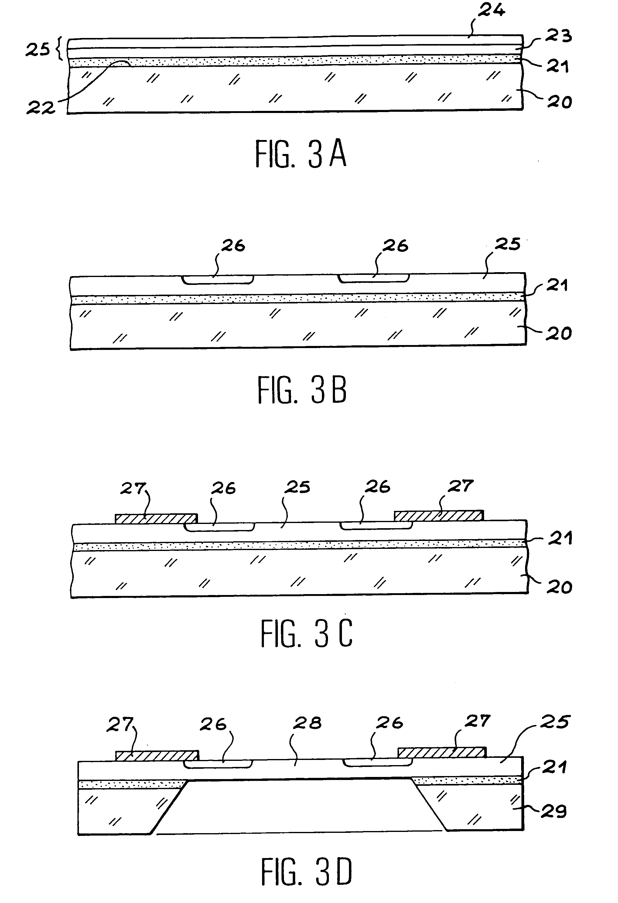
[0067] FIGS. 3A to 3D illustrate a first embodiment method for the sensing elements of pressure sensors according to the present invention,

second embodiment

[0068] FIGS. 4A to 4E illustrate a second embodiment method for the sensing elements of pressure sensors according to the present invention,

third embodiment

[0069] FIGS. 5A to 5C illustrate a third embodiment method for the sensing elements of pressure sensors according to the present invention.

DETAILED DESCRIPTION OF EMBODIMENTS OF THE INVENTION

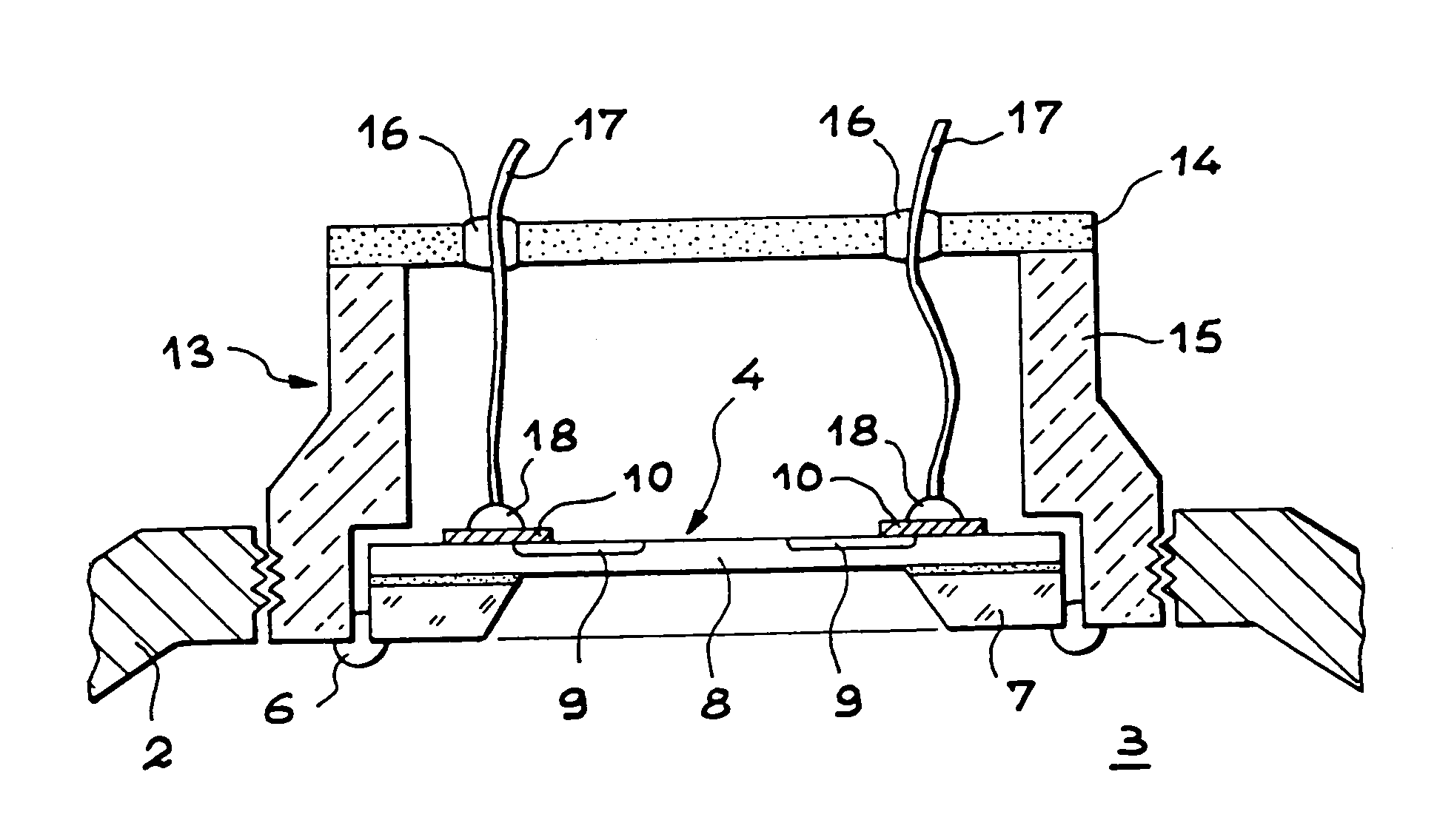
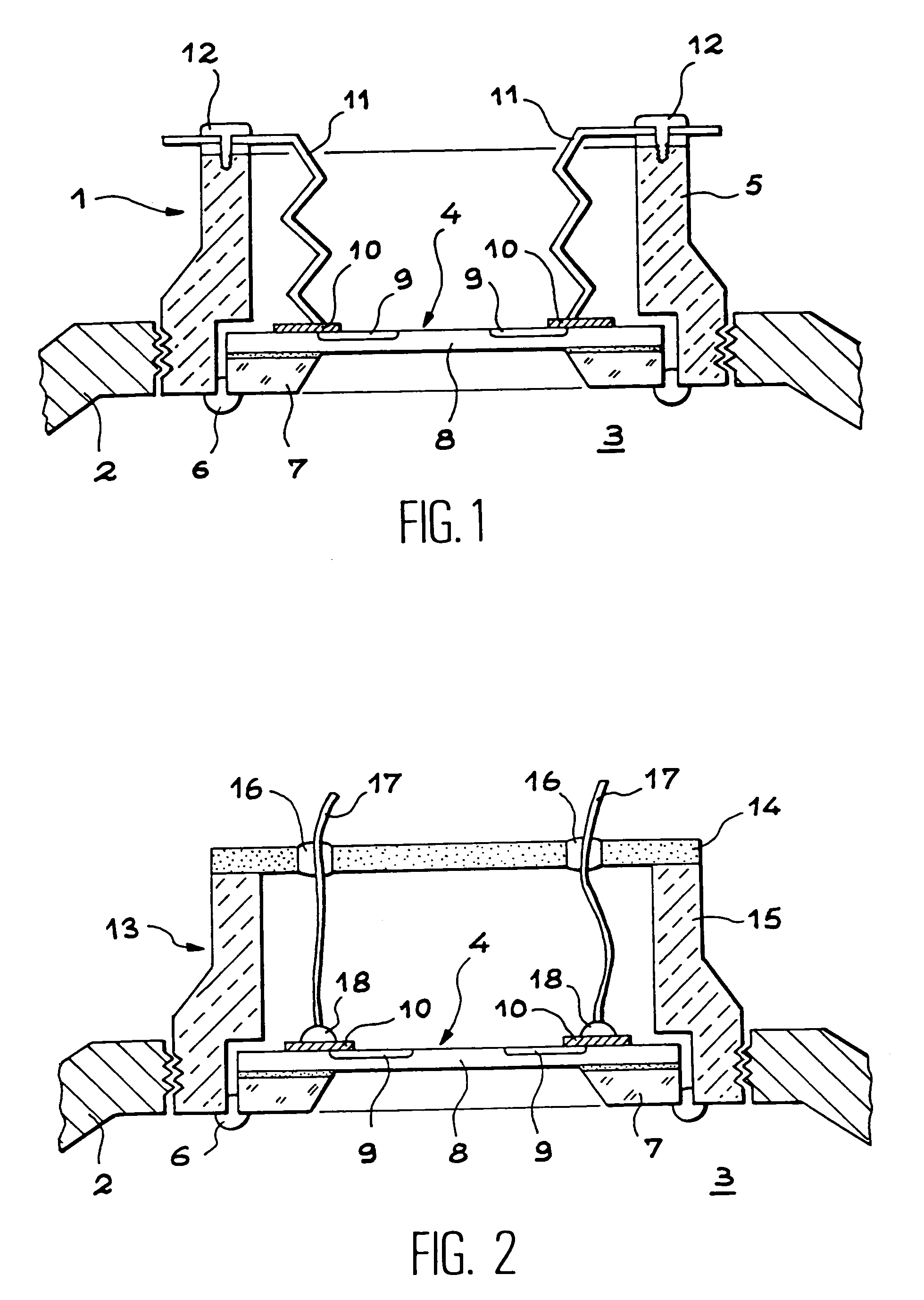
[0070] FIG. 1 shows a pressure sensor 1, according to the invention, mounted on an orifice opening into wall 2 of a reservoir (it may be an engine cylinder). The inside 3 of the reservoir contains a hostile medium whose pressure is to be measured. The pressure sensor 1 comprises a sensing element 4 fixed to one end of a carrier 5 by means of a seal strip 6.

[0071] The carrier 5, in this example of embodiment, is tubular shaped. With this shape it can be easily fixed, by screwing, into an appropriate housing in wall 2 of the reservoir. The sensing element 4 is fixed peripherally to the end of carrier 5 located on the reservoir side. The surface of the sensing element positioned towards the inside of the reservoir 2 is therefore subjected to the inner pressure of the reservoir, and the opposite sur...


PUM

PropertyMeasurementUnit
temperatureaaaaaaaaaa
temperaturesaaaaaaaaaa

Abstract

The invention concerns a pressure sensor (1), able to operate at high temperature and measure the pressure of a hostile medium, comprising: a sensing element (4) integrating a membrane (8) in monocrystalline silicon carbide, made by micro-machining a substrate in polycrystalline silicon carbide, a first surface of membrane (8) intended to contact said medium, a second surface of membrane (8) comprising membrane deformation detection means (9) connected to electric contacts (10) to connect electric connection means (11), the surfaces of sensing element (4) contacting said medium being chemically inert to this medium; a carrier (5) to support sensing element (4) so that said first surface of membrane (8) may be contacted with said medium and the second surface of membrane (8) may be shielded from said medium, carrier (5) being in polycrystalline silicon carbide; a seal strip (6), in material containing silicon carbide, brazed between carrier (5) and sensing element (4) to protect the second surface of membrane (8) from any contact with said medium.

Description

[0001] The present invention relates to a membrane pressure sensor containing silicon carbide. It also concerns the manufacture of the sensing element of the sensor.PRIOR ART[0002] With micro-electronic techniques it is possible to produce miniature pressure sensors using collective manufacturing processes. Small-sized sensors can therefore be produced at low cost. They provide the possibility of producing a sensor and its associated electronics on one same carrier.[0003] Micro-machined pressure sensors are known, made up of a silicon membrane a few tenths of a .mu.m in thickness. The difference in pressure between the two surfaces of the membrane may be detected by measuring the recess stresses by means of piezoresistive gauges obtained by ion diffusion or implantation. These piezoelectric gauges have high sensitivity and extensive mechanical stability due to the monocrystalline structure of the silicon used. Between each gauge and the substrate on which they are fabricated, electr...

Claims


Application Information

Patent Timeline
Patent Type & Authority Applications(United States)
IPC IPC(8): G01L9/00
CPCG01L9/0042G01L9/0054G01L9/0055G01L19/003Y10T29/49169G01L19/141G01L19/147Y10T29/49005G01L19/0061
Inventor CLERC, JEAN-FREDERICJAUSSAUD, CLAUDEJOLY, JEAN-PIERRETHERME, JEAN
Owner COMMISSARIAT A LENERGIE ATOMIQUE ET AUX ENERGIES ALTERNATIVES
Why Eureka
Try Eureka