Method and device for photothermal examination of microinhomogeneities

Inactive Publication Date: 2004-05-06
LAPOTKO TATIANA MS
View PDF30 Cites 141 Cited by
  • Summary
  • Abstract
  • Description
  • Claims
  • Application Information

AI Technical Summary

Benefits of technology

0007] The object of the present invention is to eliminate all said shortcomings, i.e. to increase sensitivity, spatial resolution and informative worth when examining local absorbing heterogeneities in transparent objects, as well as to determine the size of said heterogeneities even if it is smaller than the radiation wavelength used. More part

Problems solved by technology

Thus, said methods and devices cannot be used effectively to examine optically transparent objects, including biological samples in the form of live cells placed in suspension.
However, said microscopes have low sensitivity to analyze low absorption.
Beside diffraction limit on resolution (about 1 .mu.m), the shortcoming of said method is laser beam scanning on the surface of the object observed, that takes much time.
In fact, such methods allow detecting absorption from submicron zones, but they do not allow obtaining information concerning the size of said zones.
Besides, spatial resolution of s

Method used


Image

  • Method and device for photothermal examination of microinhomogeneities
  • Method and device for photothermal examination of microinhomogeneities
  • Method and device for photothermal examination of microinhomogeneities

Examples


Example

EXAMPLE 1

Study Microsamples in Diffraction Limited Image Mode

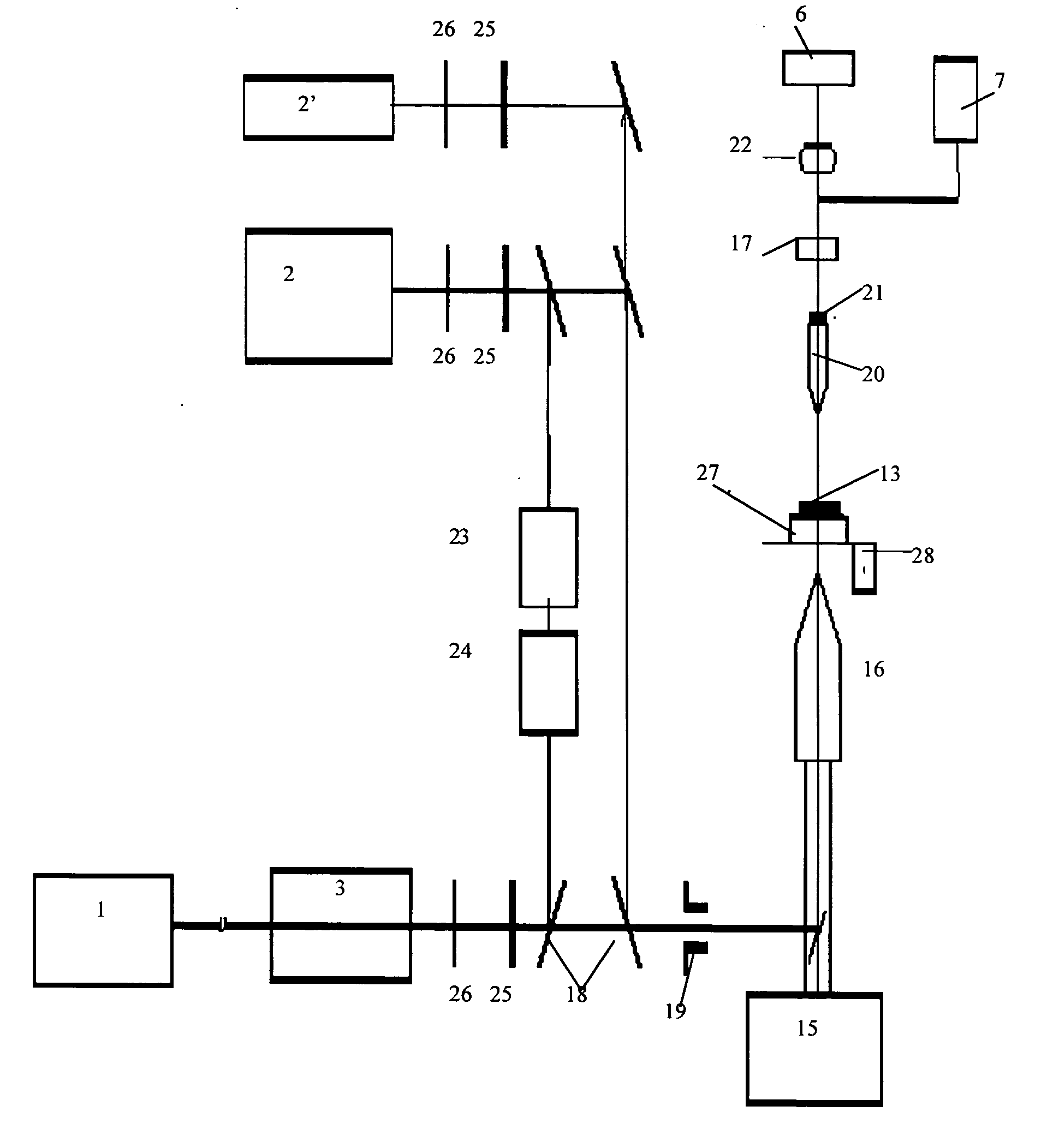
[0105] Technical basis for implementation of the device (shown in FIG. 5) is a standard optical microscope 15, equipped with unit 1 of the pump laser and unit 2 of the probe laser, photodetectors 7 and 8 and an apparatus-program device (not shown) to control the device components. The pulse pump laser of unit 1 allows irradiating the object in the visible diapason of the wavelengths ranging from 400 to 600 nm (parametrical solid state laser with the pump Nd: YAG). The pump beam is transformed to a one-mode beam using a forming unit 3 made as a spatial filter, and is focused on object 13 through an entry device 4 and a standard condenser of microscope 16. The pump irradiation is blocked by filter 17 after the object has been propagated. A probe laser 2 is a dye pulse laser having the duration of 6 ns and the wavelength of 630 nm and the energy regulated in the range of 1-100 nJ and focused (as an analogue to the pump beam) ...

Example

EXAMPLE 2

Implementation of a Laser Photothermal Microscope to Examine Biological Micro-Objects

[0119] 2.1 Active diagnostics. When examining biological objects of a single cell type, the definition of active diagnostics in the method claimed is significantly widened and even partly altered. The reason is that it assumes not only examination of the value of thermal effects induced by radiation, but also examination of the cells' reaction to the dynamic (short-time) thermal excitement. It is important for many applications, and more particularly for the objects of laser medicine, laser safety and examination of the fundamental cell properties, examination of external effects including radiation, etc. The method for examination in this case is examining and comparing cells' reactions to various energies of the laser pump. Said reactions could be examined using both independent methods, e.g. biochemical and histological, and the pofotothermal method itself. The measurement scheme and the...

Example

EXAMPLE 3

The Mode for Photothermal Measurement of Submicron Microheterogeneities

[0135] One of the issues of intensively developing nanotechnologies in various scientific and technical fields is the lack of precise control of the technological processes forming new structures with the resolution capacity as large as a few run. The method claimed allows solving the problem using high resolution provided by the change of the nanostructures' cooling speed using the sources of laser radiation. An example for practical realization: the pump laser unit: a femtosecond pulse laser Cr:LiSAF, wavelengths, 850 nm in particular, energy range 1 .mu.J-3 mJ, pulse width 10.sup.-13 sec., the delay unit being realized as an optical delay line, a part of the pump beam being used as a probe beam. The expected resolution is 1-5 nm. Beside visualization of nanostructures, the device claimed also provides for the accomplishing of the control function and the impact function due to the strong interaction w...


PUM


Abstract

The invention relates to optical microscopy, in particular to methods for photothermal examination of absorbent microinhomogeneities using laser radiation sources and can be widely used in laser engineering, industry and biomedicine for examining relatively transparent objects containing submicron impurities, including the detection of local inclusions and defects in ultrapure optical and semiconductor materials and the non-destructive diagnosis of biological samples on a cellular and subcellular level. The aim of the invention is to increase the sensitivity, spatial resolution and informativity of examination of local absorbent microinhomogeinities in transparent objects and to measure said microinhomogeinities even when they are less than the used emission wavelength. The inventive method consists in radiating a sample with a pumping laser beam. The duration of the radiation is equal to or less than a representative time for cooling the examined microinhomogeinity. The relatively large surface of the sample is radiated, the shape thereof being greater than the wavelength of the used pumping laser. Thermal variations of the refractive index occurring in the sample as a result of absorption produced with the aid of the pumping beam are recorded by measuring parameters of a test laser beam. The diameter of the test beam is chosen in such a way that it is equal to or greater than the diameter of the pumping beam. A diffraction-limited phase distribution along the cross-section of the testing laser beam is transformed into an amplitude image, the microinhomogeinity properties being determined by measuring said amplitude image.

Description

[0001] The invention relates to optical microscopy, and more particularly to the methods for photothermal (PT) examination of absorbing microheterogeneities using laser radiation, and can be widely used to examine transparent objects with absorbing submicron fragments in laser technique, industry, and biomedicine, including detection of local impurities and defects in super-pure optical and semiconducting materials and non-destructive diagnostics of biological samples on cellular and sub-cellular levels.TECHNICAL LEVEL[0002] There are known numerous methods for optical examination of microheterogeneities using optical microscopes of various modifications, including methods with the use of lasers. In the general, said methods and the corresponding devices have a diffraction limit on resolution or allow examining the object's image by high spatial resolution right up to separate molecules, but as a rule, only on the surface of solid samples. Thus, said methods and devices cannot be us...

Claims


Application Information

Patent Timeline
IPC IPC(8): G01N21/17
CPCG01N21/171
Inventor LAPOTKO, DMITRI OLEGOVICHZHAROV, VLADIMIR PAULOVICH
Owner LAPOTKO TATIANA MS
Why Eureka
Try Eureka