Microscopy system, microscopy method and a method of treating an aneurysm

Active Publication Date: 2004-06-10
KLINIKUM DER JOHANN WOLFGANG GOETHE UNIVET FRANKFURT +1
View PDF18 Cites 158 Cited by
  • Summary
  • Abstract
  • Description
  • Claims
  • Application Information

AI Technical Summary

Problems solved by technology

It is, however, not possible to perceive surrounding regions of this tissue.
However, such illumination with visible light is not possible since the laser light source does not provide such light, and the band-pass filter in the beam path of the light source blocks such visible light from incidence on the tissue.
Such different shadows render it more difficult to correctly associate regions of the fluorescent image with regions of the visible image of the tissue region.
Such procedure is complicated and requires a high power of concentration of the observer since he must remember the im

Method used


Image

  • Microscopy system, microscopy method and a method of treating an aneurysm
  • Microscopy system, microscopy method and a method of treating an aneurysm
  • Microscopy system, microscopy method and a method of treating an aneurysm

Examples


Embodiment Construction

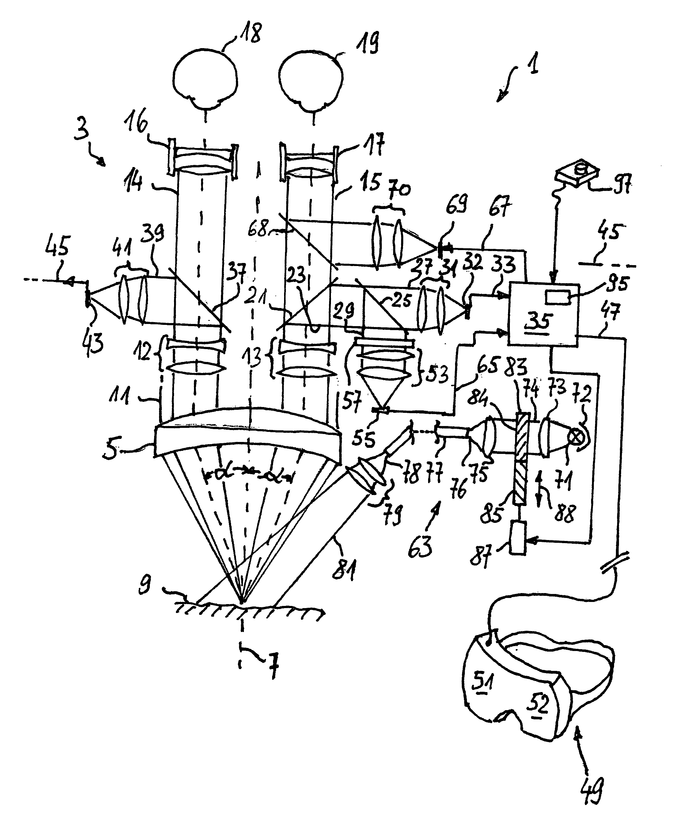
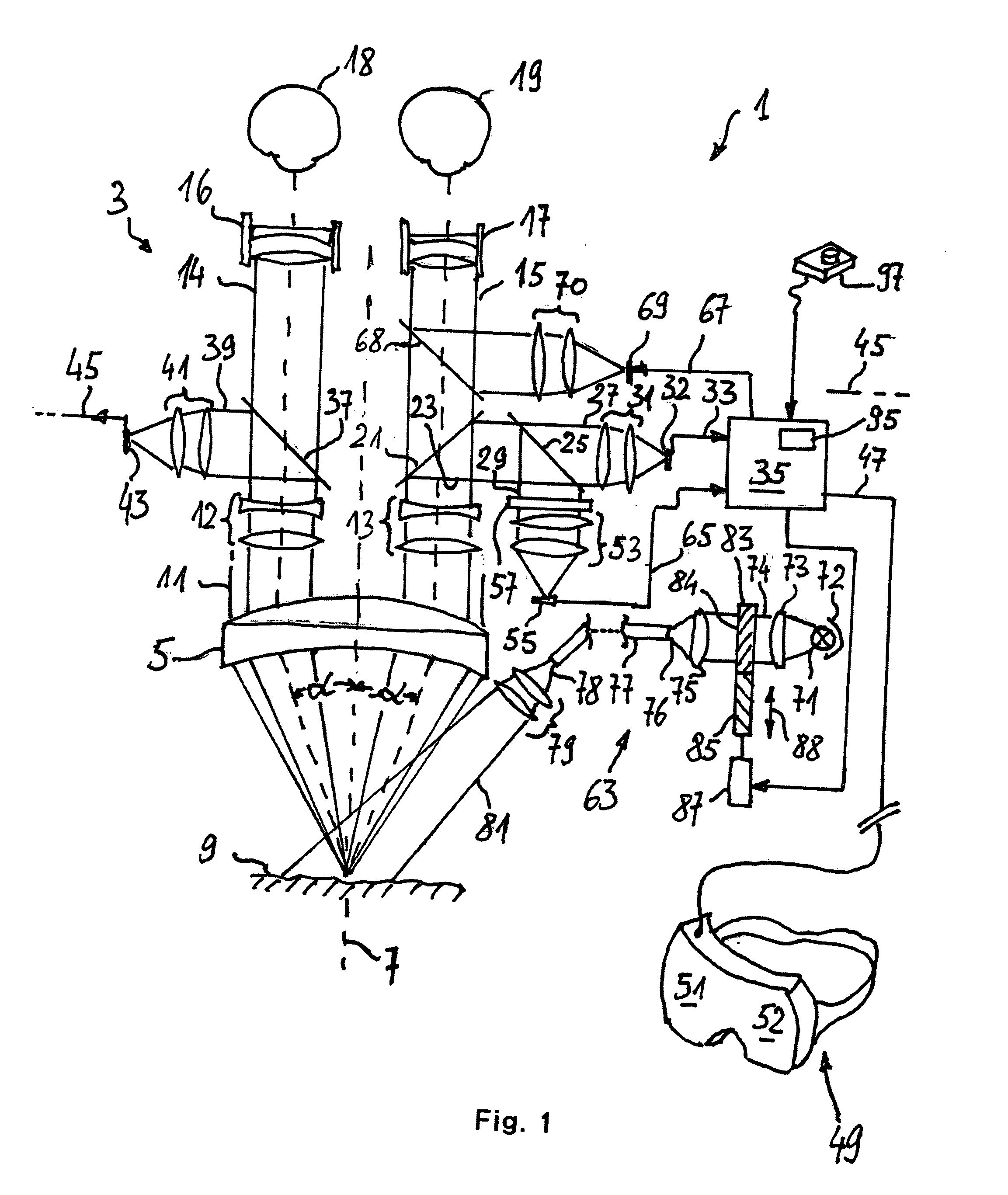
[0064] FIG. 1 schematically shows a microscopy system 1 comprising a microscopy optics 3 including an objective lens 5 having an optical axis 7. An object 9 to be inspected is disposed in an object plane of objective lens 5. Light emanating from the object 9 is transformed by the objective lens 5 to form a parallel beam 11 in which two zoom systems 12, 13 are disposed at a distance from the optical axis 7. The zoom systems 12, 13 use partial beams 14 and 15 of the parallel beam 11 and supply the partial beams 14, 15 to oculars 16 and 17 through deflecting prisms (not shown in FIG. 1) of a body of a tube of the microscopy system 1. A user may perceive a magnified representation of the object 9 as an image when looking into the oculars 16, 17 with his left eye 18 and right eye 19, respectively. The image perceived with the left eye 18 corresponds to an image when looking onto the object under an angle .alpha. with respect to the optical axis, and the image perceived with the right eye...


PUM


Abstract

A microscopy system and a microscopy method are provided for observing a fluorescent substance accumulated in a tissue. The microscopy system comprises a filter allowing to observe the tissue at a same time both with visible light and with fluorescent light. It is possible to observe a series of previously recorded fluorescent light images in superposition with the visible light images. An end of the series of images may be automatically determined. A thermal protective filter may be inserted into a beam path of an illuminating system at such automatically determined end of the series. Further, the fluorescent light image may be analyzed for identifying a coherent fluorescent portion thereof. A representation of a periphery line of the coherent portion may be generated, and depths profile data may be obtained only from the coherent portion. An illuminating light beam for exciting the fluorescence may be modulated for improving a contrast of fluorescent images.

Description

[0001] 1. Field of the Invention[0002] The invention relates to a microscopy system and a microscopy method which may be in particular used for observing an emission of fluorescent light at wavelengths of the near infrared and / or infrared. Further the invention relates to a method of treating an aneurysm.[0003] Fluorescent substances and fluorescent dyes showing a fluorescence at wavelengths in a region of the near infrared or infrared are used in medical applications for various purposes such as visualizing particular types of tissue, tissue structures and tissue functions. Herein, a fluorescent substance or dye or a precursor of such fluorescent substance or dye is applied to a patient under examination. The dye accumulates in particular types of tissue and tissue structures, and by observation of the fluorescent light such types of tissue and tissue structures, respectively, may be visualized and identified by an observer. Optical tools are used to visualize the some times weak i...

Claims


Application Information

Patent Timeline
IPC IPC(8): A61B5/00G01N21/64G02B21/00G02B21/16G02B21/18G02B21/36
CPCA61B5/0066G01N21/6428A61B5/0086G02B7/002G02B21/16G02B21/18G02B21/361G02B21/365G02B21/368G02B27/0172G02B2027/0134G02B2027/0138G02B2027/014G01N21/359G02B21/20G01N2021/6421G01N2021/1782G01N21/6458G02B21/367G01N21/4795G01N21/3563G01N21/35A61B5/0071G02B21/22
Inventor HAISCH, MICHAELHAUGER, CHRISTOPHWOLF, HARTMUTHUG, JOACHIMBRIGITTA, SCHWARZGAIDA, GERHARDRAABE, ANDREAS
Owner KLINIKUM DER JOHANN WOLFGANG GOETHE UNIVET FRANKFURT
Why Eureka
Try Eureka