Cutter wheel, device and method using the cutter wheel, method of dividing laminated substrate, and method and device for manufacturing cutter wheel

a technology of cutter wheels and cutter wheels, which is applied in the direction of manufacturing tools, transportation and packaging, paper/cardboard containers, etc., can solve the problems of difficult removal of all, corrosion of the metallic parts of the organic el device, and not always preferable dicing

Inactive Publication Date: 2004-07-01
MITSUBOSHI DIAMOND IND CO LTD
View PDF1 Cites 21 Cited by
  • Summary
  • Abstract
  • Description
  • Claims
  • Application Information

AI Technical Summary

Benefits of technology

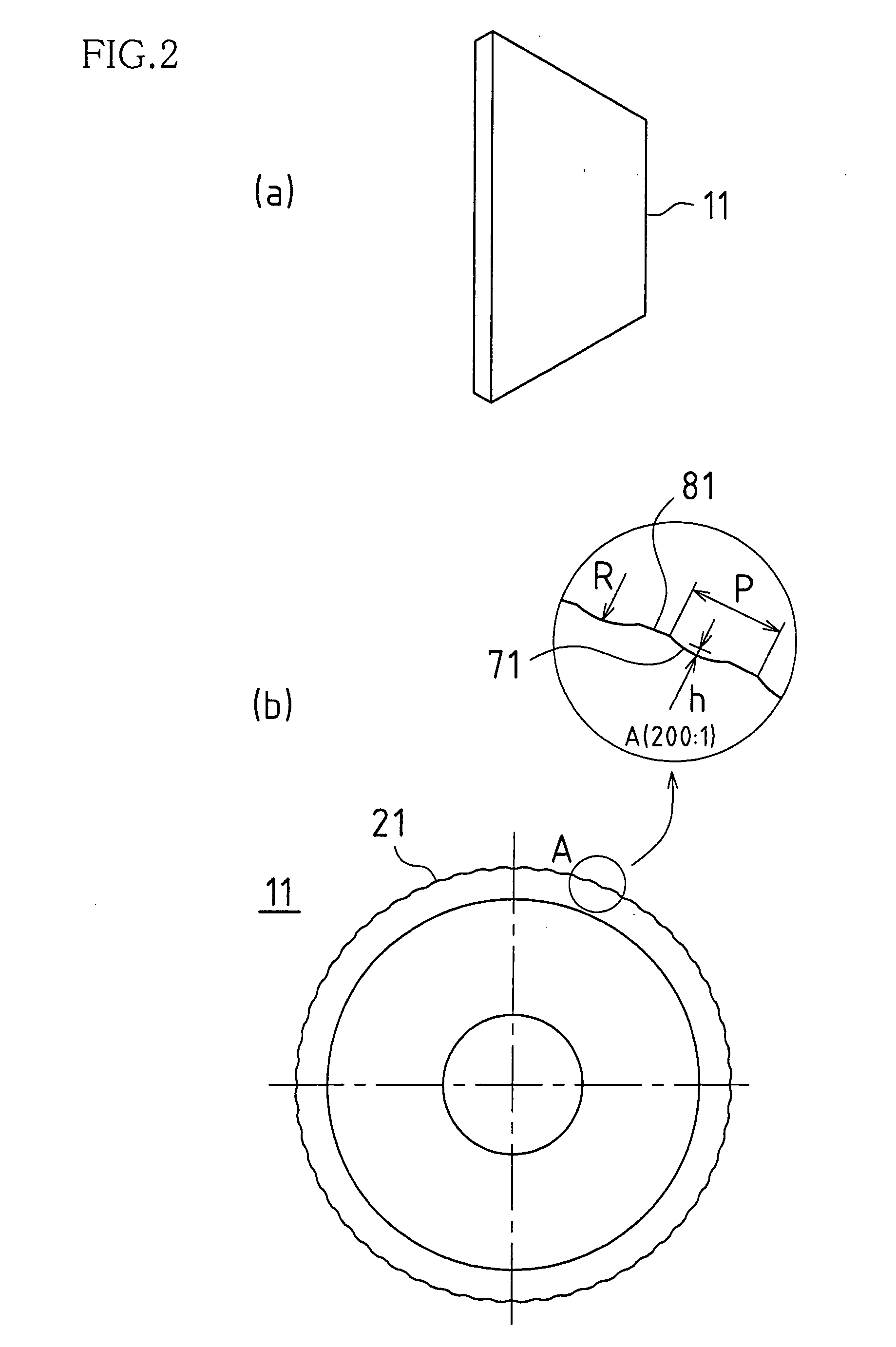
[0046] In this case, compared to a conventional cutter wheel without protrusions at the blade-edge ridge, when scribing with a cutter wheel of the present invention that has protrusions, an extremely long vertical crack can be produced that almost passes through the thickness of the brittle substrate. The reason for this seems to be that, during the rotation of the cutter wheel, the protrusions of the blade-edge ridge apply intermittent impacts to the substrate, and because the protrusions deeply cut into the glass panel. Furthermore, there is the advantage that it is difficult for unnecessary horizontal cracks to occur at the surface of the brittle substrate. The likely reason for this is that the cutting of the cutter wheel into the brittle substrate centers on the point contact of the protrusions, and therefore there is less stress on the surface of glass panel during scribing compared to a conventional cutter wheel. Furthermore, as the protrusions cut into the glass panel, the cutter wheel has zero slip, and therefore none of the troubles that accompany slippage such as abrasion.
[0135] As shown in FIG. 8, the cutter wheel 6 is provided with an area A in which grooves are formed at the blade-edge ridge portion, and an area B in which grooves are not formed. In consideration of the workability of forming grooves at the ridge of the cutter wheel 16, it is preferable that the proportion of the area A in which such grooves are formed to the entire periphery of the ridge portion (area A+area B) (hereafter "proportion of area A to the entire periphery") is not greater than three-quarters. With such proportions, a cutter wheel with superior workability can be achieved without requiring a long processing time for forming grooves.

Problems solved by technology

However, with dicing, frictional heat is produced in the area in which the blade is machining, and machining is performed while supplying a coolant to this area, so that dicing is definitely not always preferable for organic EL devices, which have metallic portions such as a metallic electrode layer and metallic terminals.
That is, in the case of dicing, it is in fact very difficult to remove all of the coolant after dicing, and when there is residual water due to incomplete coolant removal, there is the risk of corrosion occurring in the metallic portions of the organic EL device.
Furthermore, the cutting time of dicing is longer compared to scribing, and thus there is the problem of poor productivity.
With scribing, however, there are problems of a completely different nature from dicing.
Namely, unlike dicing, scribing is difficult when there is a thin film on the substrate, so when cutting and separating with scribing, convex portions and thin films that include light-emitting portions are formed on the surface of the substrate with intervals in which the cutter wheel can be inserted.
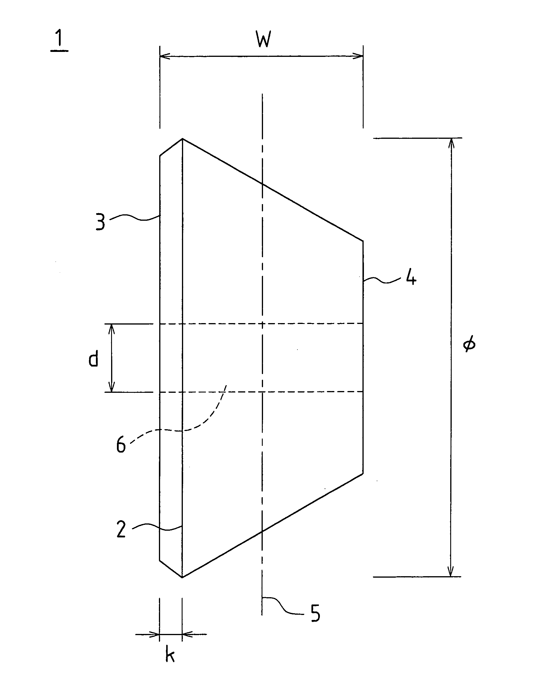
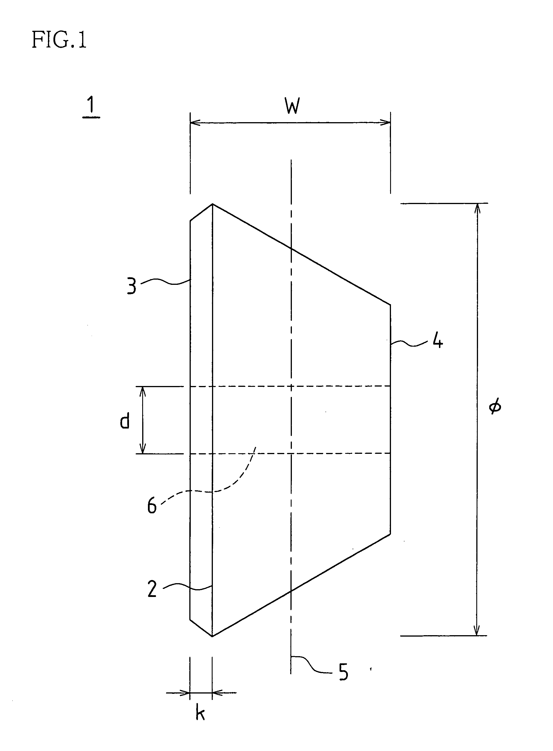
Therefore, scribing is performed with a cutter wheel on the substrate surface that is exposed between the convex portions and the thin film, but, as shown in FIG. 28, a conventional cutter wheel H has a blade-edge ridge C at the center between the side faces of the wheel, so that the scribing position S must be in a location sufficiently away from the convex portions and thin film X so that the cutter wheel H does not interfere with the convex portion or thin film X. However, when the scribing position S is a position away from the convex portion or thin film X in this way, there is the problem that the area for each device on the substrate becomes larger than necessary.
However, when the pressing force of the breaker bar 73 is too strong, there is the risk that the upper-side glass substrate 7B will break at the same time.
Furthermore, there is also the risk that fissured portions will collide and cause fragmentation (horizontal cracking) in that location.
A bonded glass substrate in which such a diagonally scribe-broken surface or fragmentation has been produced loses its commercial value as a liquid crystal panel.
The above-described glass cutter wheel provided with depressions and protrusions at the ridge portion can greatly improve scribing performance compared with conventional glass cutter wheels, but as it is formed with precise depressions and protrusions along the entire periphery of its ridge portion, and because considerable time is required to work and form the depressions and protrusions at the ridge portion, there are workability problems.
Whether few or many in number, chips (cullets) are unavoidably produced in the scribing process.
And when such cullets remain on a bonded glass substrate, abrasion can be caused to the bonded glass substrate, thus becoming a cause of damage to the quality of the bonded glass substrate.
However, operations to remove the cullets produced in scribing are troublesome, and moreover, at times it is very difficult to completely remove the cullets.
Furthermore, there is the problem that the surface of the glass substrate may be scratched by cullet removal.
Such scratching is not desirable for a liquid crystal display glass substrate, but especially for projector substrates, even slight scratches are enlarged when projected, reducing the substrate's quality as a projector substrate, and thus reliability cannot be secured, and the yield is reduced.

Method used


Image

  • Cutter wheel, device and method using the cutter wheel, method of dividing laminated substrate, and method and device for manufacturing cutter wheel
  • Cutter wheel, device and method using the cutter wheel, method of dividing laminated substrate, and method and device for manufacturing cutter wheel
  • Cutter wheel, device and method using the cutter wheel, method of dividing laminated substrate, and method and device for manufacturing cutter wheel

Examples


embodiment 1

[0191] FIGS. 25(a) to (d) are cross sections that illustrate each step in a second method of scribe-breaking the bonded glass substrate 10 using a scribe-breaking apparatus provided with a glass cutter wheel 1 of the present invention. It should be noted that, for convenience, the glass substrate of one side of the bonded glass substrate, which is a liquid crystal mother substrate, formed by bonded a pair of glass substrates facing together is taken as glass substrate 10A, and the glass substrate of the other side is taken as glass substrate B in the following explanation.

[0192] (1) First, as shown in FIG. 25(a), the bonded glass substrate 10 is mounted on a first scribing apparatus with the glass substrate 10A of the bonded glass substrate 10 facing up, and a scribe line Sc is formed on the glass substrate 10A by scribing using the cutter wheel 1 (or 15 / 16).

[0193] (2) Next, the bonded glass substrate 10 on which the scribe line Sc has been formed on the glass substrate 10A is turn...

working example 1

[0200] FIGS. 26(a) to (i) are process drawings for describing Working Example 1 of the present invention. Furthermore, FIG. 27 includes schematic drawings that show a configuration of the apparatuses used in such a process. FIG. 27(a) shows an example in which the apparatuses of the process are configured in a simplified line. And FIG. 27(b) is an example in which the apparatuses are configured around a transport robot. The present invention is applied to a method of scribe-breaking a flat display panel mother glass substrate 80 formed by bonded together glass substrates that are one kind of a brittle material substrate. The glass substrate on one side of the flat display panel mother glass substrate 80 is taken as glass substrate 80A, and the glass substrate on the other side is taken as glass substrate 80B, and the material of the glass of the glass substrate 80A and the glass substrate 80B is non-alkali glass for example. Furthermore, the cutter wheel used is the cutter wheel 16 ...

working example 2

[0212] The following is an explanation of a working example in which the present invention is applied to a method of scribe-breaking a reflective-type projector substrate formed by bonded together a glass substrate that is one kind of a brittle material substrate and a silicon substrate. The glass substrate on one side of the reflective-type projector substrate is taken as glass substrate 80A, and the silicon substrate on the other side is taken as silicon substrate 80C, with the material of the glass of the glass substrate 80A taken as a non-alkali glass for example. Furthermore, the cutter wheel used is the cutter wheel 16 of FIG. 8 that can obtain cracks in which the depth of the vertical crack is periodically varied within the glass substrate.

[0213] The vertical cracks obtained during scribing the silicon substrate 80C with the cutter wheel 16 of FIG. 8 are continuously shallow.

[0214] Consequently, by only substituting the silicon substrate 80C for the glass substrate 80B of FIG...


PUM

PropertyMeasurementUnit
diameteraaaaaaaaaa
diameteraaaaaaaaaa
diameteraaaaaaaaaa

Abstract

A cutter wheel 1 is formed with an insertion through-hole 6 at the center of the wheel, along with a blade-edge ridge 2 that is displaced to one side face from a center 5 between between wheel side faces 3 and 4. The larger the extent of displacement of the blade-edge ridge 2, that is, the greater the distance from the center 5 until the blade-edge ridge 2, or in other words, the smaller the distance between the left-side face 3 and the blade-edge ridge 2, the closer scribing can be performed to the convex portion and thin film X of the devices during scribing.

Description

[0001] The present invention relates to cutter wheels that are scribing cutters used for forming scribe lines on brittle materials, as well as scribing apparatus that are equipped with such cutter wheels, scribing methods by which scribe lines are formed for the purpose of scribe-breaking brittle materials, and scribe-breaking methods for bonded substrates, as well as cutter wheel manufacturing methods and apparatus for producing cutter wheels.[0002] Brittle materials includes such materials as glass, semiconductor wafers, ceramics, and so on used in glass substrates, bonded glass substrates, and the like.[0003] In comparison to displays that use liquid crystal display devices (LCD), organic electroluminescent (EL) displays that use organic EL devices do not need a backlight as they are self light-emitting, and for this reason they are also enabling ever thinner display designs. Furthermore, as they have many other advantages such as low power consumption and speedy responsiveness, ...

Claims


Application Information

Patent Timeline
Patent Type & Authority Applications(United States)
IPC IPC(8): B28D1/22B28D5/00C03B33/033C03B33/037C03B33/07C03B33/10
CPCB28D1/225B28D5/0011C03B33/033C03B33/107C03B33/07C03B33/074C03B33/037Y02P40/57Y10T83/0341Y10T83/0385
Inventor MAEKAWA, KAZUYASOYAMA, HIROSHI
Owner MITSUBOSHI DIAMOND IND CO LTD
Why Eureka
Try Eureka