Optical recording medium

a technology of optical recording medium and optical recording medium, which is applied in the direction of mechanical recording, flat record carrier container, instruments, etc., can solve the problems of inability to increase the thickness of optical recording medium, inability to sufficiently increase the thickness of transparent intermediate layer between neighboring information recording layer, and inability to achieve interlayer crosstalk inevitably increasing

Active Publication Date: 2004-07-15
TDK CORPARATION
View PDF1 Cites 73 Cited by
  • Summary
  • Abstract
  • Description
  • Claims
  • Application Information

AI Technical Summary

Benefits of technology

[0011] According to the present invention, neighboring transparent intermediate layers facing each other across an information recording layer have different thicknesses, so that when a laser beam is projected onto the information recording layer farther from the light incidence plane among the neighboring information recording layers to reproduce data therefrom, the laser beam reflected from the information recording layer located on the side of the light incidence plane with respect to the information recording layer onto which the laser beam is focused is not focused onto any other information recording layer and, therefore, it is possible to effectively prevent generation in the reproduced signal of significant interlayer cross-talk owing to the laser beam focused onto the information recording layer from which data are to be reproduced being projected onto other information recording layers.

Problems solved by technology

However, it is not feasible to increase the thickness of an optical recording medium owing to the need to ensure compatibility with optical recording medium already in practical use and it is therefore impossible to sufficiently increase the thickness of the transparent intermediate layers between neighboring information recording layers.
As a result, in an optical recording medium including three or more information recording layers, interlayer cross talk inevitably increases as the number of information recording layers increases.
However, if a transparent intermediate layer is formed too thin, interlayer cross-talk between information recording layers located on the opposite sides of the transparent intermediate layer becomes great.

Method used


Image

  • Optical recording medium
  • Optical recording medium
  • Optical recording medium

Examples


working example 1

[0132] An optical recording medium sample #1 was fabricated in the following manner.

[0133] A disk-like polycarbonate substrate having a thickness of 1.1 mm and a diameter of 120 mm and formed with grooves and lands on the surface thereof was first fabricated by an injection molding process so that the track pitch (groove pitch) was equal to 0.32 .mu.m.

[0134] Then, the polycarbonate substrate was set on a sputtering apparatus and a reflective film consisting of an alloy of Ag, Pd and Cu and having a thickness of 100 nm, a second dielectric film containing a mixture of ZnS and SiO.sub.2 and having a thickness of 39 nm, a second L0 recording film containing Cu as a primary component, added with 23 atomic % of Al and 13 atomic % of Au and having a thickness of 5 nm, a first L0 recording film containing Si as a primary component and having a thickness of 5 nm and a first dielectric film containing the mixture of ZnS and SiO.sub.2 and having a thickness of 20 nm were sequentially formed o...

working example 2

[0148] An optical recording medium sample #1 was fabricated in the following manner.

[0149] A disk-like polycarbonate substrate having a thickness of 1.1 mm and a diameter of 120 mm and formed with grooves and lands on the surface thereof was first fabricated by an injection molding process so that the track pitch (groove pitch) was equal to 0.32 .mu.m.

[0150] Then, the polycarbonate substrate was set on a sputtering apparatus and an L0 layer having a thickness of 32 nm was formed on the surface of the polycarbonate substrate on which the grooves and lands were formed, by the sputtering process using a target of the mixture of ZnS to SiO.sub.2 and a target of Mg so as to contain the mixture of ZnS to SiO.sub.2 at the mole ratio of 50:50.

[0151] Further, the polycarbonate substrate formed with the L0 layer on the surface thereof was set on a spin coating apparatus and the L0 layer was coated with a resin solution prepared by dissolving acrylic ultraviolet curable resin in a solvent to f...

working example 3

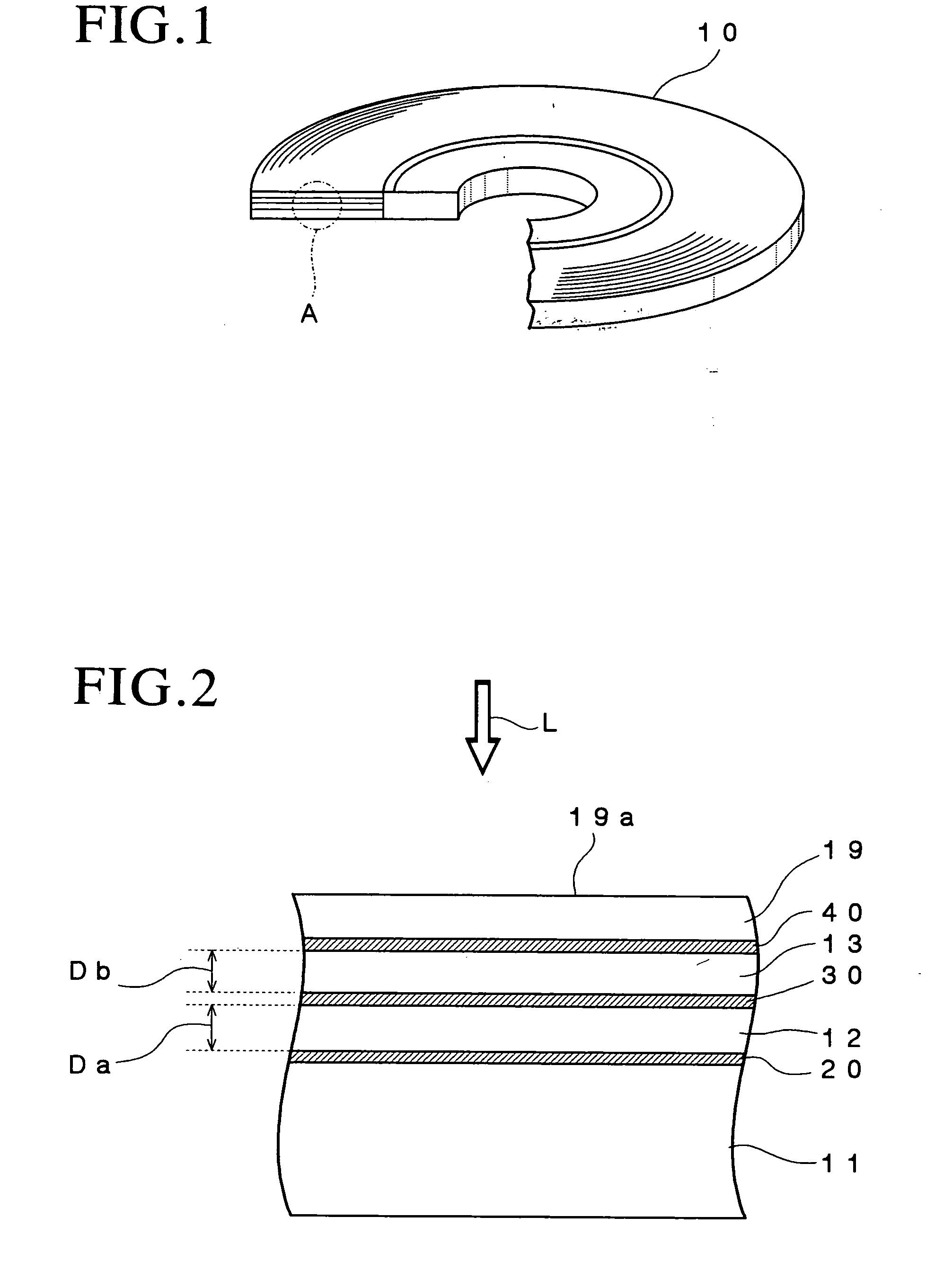
[0164] Optical recording samples #3-1 to #3-15 were fabricated in the manner of Working Example 2 except that the first transparent intermediate layer and the second transparent intermediate layer were formed so that the total thickness thereof was 40 .mu.m and that the thickness Db of the second transparent intermediate layer was varied in increments of 2.5 .mu.m from 2.5 .mu.m to 37.5 .mu.m.

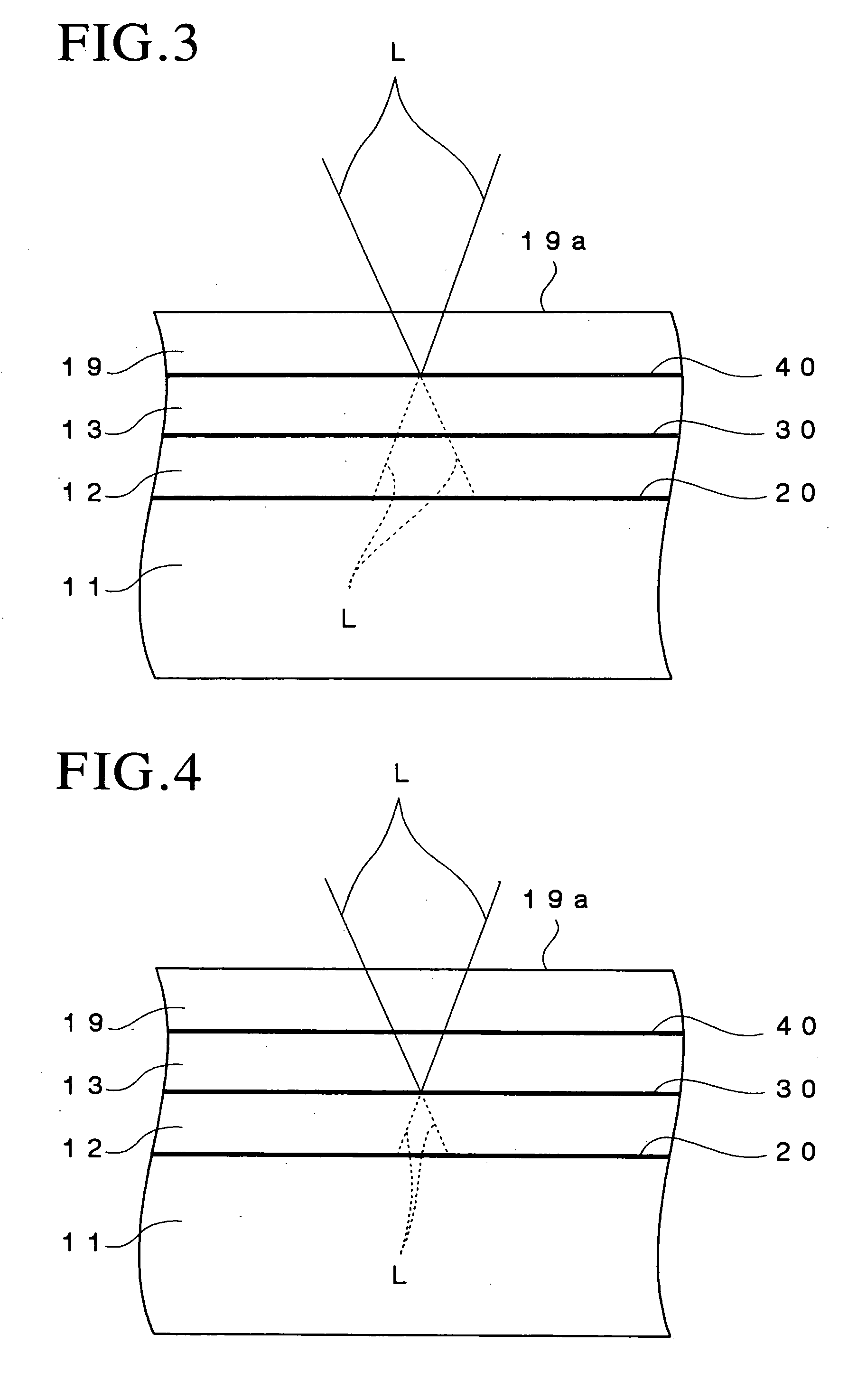
[0165] Each of the thus fabricated optical recording medium samples #3-1 to #3-15 was set in a DDU1000 optical recording medium evaluation apparatus manufactured by Pulstec Industrial Co., Ltd. and a laser beam having a wavelength of 405 nm was focused onto each of the L0 layers using an objective lens whose numerical aperture was 0.85 via the light transmission layer while each sample was rotated at a linear velocity of 5.3 m / sec, thereby recording 8 T signals therein and the laser beam was focused onto each of the L1 layers via the light transmission layer, thereby recording 8 T signals there...


PUM

PropertyMeasurementUnit
thicknessaaaaaaaaaa
outer diameteraaaaaaaaaa
thicknessaaaaaaaaaa

Abstract

An optical recording medium includes a substrate, a protective layer, three or more information recording layers formed between the substrate and the protective layer and transparent intermediate layers each formed between neighboring information recording layers and capable of recording data in the three or more information recording layers and reproducing data recorded in the three or more information recording layers by projecting a laser beam onto the three or more information recording layers via a light incidence plane constituted by the surface of either the substrate or the protective layer, wherein neighboring transparent intermediate layers facing each other across an information recording layer have different thicknesses. According to the thus constituted optical recording medium, it is possible to reduce interlayer cross-talk.

Description

[0001] The present invention relates to an optical recording medium, and particularly, to an optical recording medium which includes three or more information recording layers and reduces interlayer cross-talk.DESCRIPTION OF THE PRIOR ART[0002] Optical recording media such as the CD, DVD and the like have been widely used as recording media for recording digital data. Such optical recording media require improvement in ability to record large amounts of data and various proposals have been made in order to increase the data recording capacity thereof.[0003] One of these is an optical recording medium having two information recording layers and such an optical recording medium has been already put to the practical use as an optical recording medium adapted to enable only data reading, such as the DVD-Video and the DVD-ROM.[0004] An optical recording medium adapted only for reading data and provided with two information recording layers is formed by laminating two substrates each havi...

Claims


Application Information

Patent Timeline
Patent Type & Authority Applications(United States)
IPC IPC(8): G11B7/24G11B7/24038G11B7/24067G11B7/2542G11B7/256G11B7/2572G11B7/26
CPCG11B7/24G11B2007/24324G11B7/2433G11B7/2531G11B7/2533G11B7/2534G11B7/2536G11B7/2542G11B7/2572G11B7/259G11B7/263G11B2007/24304G11B2007/24308G11B2007/2431G11B2007/24312G11B2007/2432G11B2007/24322G11B7/24038
Inventor MISHIMA, KOJIUTSUNOMIYA, HAJIMEINOUE, HIROYASUKOMAKI, TSUYOSHIYAMADA, TAKASHI
Owner TDK CORPARATION
Why Eureka
Try Eureka