Staged heat and mass transfer applications

a heat and mass transfer and stage technology, applied in distillation separation, fractional distillation, boiler/still distillation, etc., can solve the problems of few vents, if any, worth recovering, and few successful recovery evidence, so as to improve overall operability and reliability, enhance control robustness, and reduce operating and maintenance costs

Inactive Publication Date: 2004-09-02
TUNG PETER
View PDF10 Cites 16 Cited by
  • Summary
  • Abstract
  • Description
  • Claims
  • Application Information

AI Technical Summary

Benefits of technology

0021] Accordingly, several objects and advantages of this invention are:
0022] The present invention focuses on improving overall operability and reliability at recovering steam vent from a deaerator system.
0023] The present invention enhances control robustness with intrinsic safety features to guard against purge gas reentry to the deaerator.
0024] The present invention focuses on ways to lower operating and maintenance costs in deaerator vent recovery by incorporating hydraulic and pressure self-balancing design features.
0025] The present invention focuses on minimizing installation and equipment costs by capitalizing on available system hydraulics to enable recovery process to work in tandem with deaerator systems at any operating pressure.
0026] The present invention focuses on ways to improve overall quality of deaerator outlet flow and handling capacity to postponed costly capacity increases.

Problems solved by technology

Despite the obvious latent heat and condensate values in the steam, and perhaps the added cost impact of fugitive emissions of process elements like odor and products, there is few evidence of successful recovery due to many technical challenges inherent in these vents.
Few vents, if any, are worth recovering due to these variability and lower heat quality.
Ice buildups are nuisance and pose safety hazards during sub-zero weather conditions.
The resulting condensate from the condensed steam, after coming into direct contact with the moist air from the dryers, can no longer be recycled as boiler feed water because of cross contamination.
Alternatively, if the vent were to be kept free of contaminates by a closed chamber not vented to atmosphere, inadvertent over condensing could create a vacuum situation risking implosion of the vessel.
Vacuum breakers to prevent such risk would introduce atmospheric oxygen to cause extensive corrosion.
Consequently, efforts to recover these vents face many not readily apparent difficult challenges.
This similarity points to an underlying difficulty not readily apparent.
Very quickly, trying to replace this very "convenient" pressure regulation becomes a tall task.
This heat flow to the heat sink results in some steam being condensed.
The resulting oxygen entering these vessels would cause corrosion.
This risk of corrosion is most pronounced when the flow of flashing steam drops during intermittent flashing, while the cooling coil is continuously trying to remove heat, subcooling the condensate in the process.
This requires control and instrumentation, which adds to reliability concerns, capital, operating, and maintenance costs.
Besides, residual heat remaining in the vent stream is not being recovered.
These additional complications further deter feasibility and pose added risk of implosion as described earlier.
Naturally, heat sink capacities associated with vent recovery have practical limits, both in rate and temperature approach.
It would be impractical to size for abnormal heat load conditions.
Incidentally, pressure Safety Valves (PSV) are very expensive for low discharge pressure driving force available for relief, even if the vessel can be rated for a higher operating pressure.
Once the atmosphere venting option is removed, challenges keep multiplying.

Method used


Image

  • Staged heat and mass transfer applications
  • Staged heat and mass transfer applications
  • Staged heat and mass transfer applications

Examples


Embodiment Construction

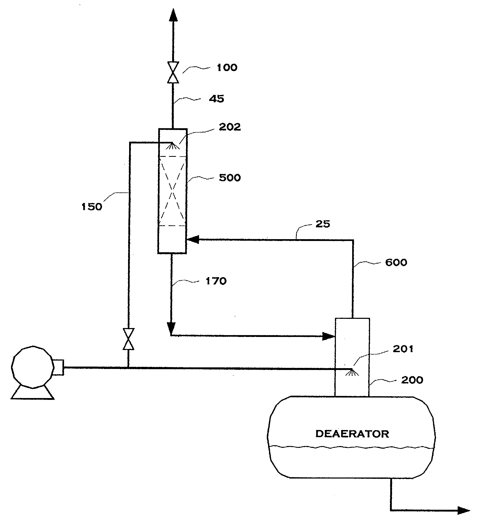
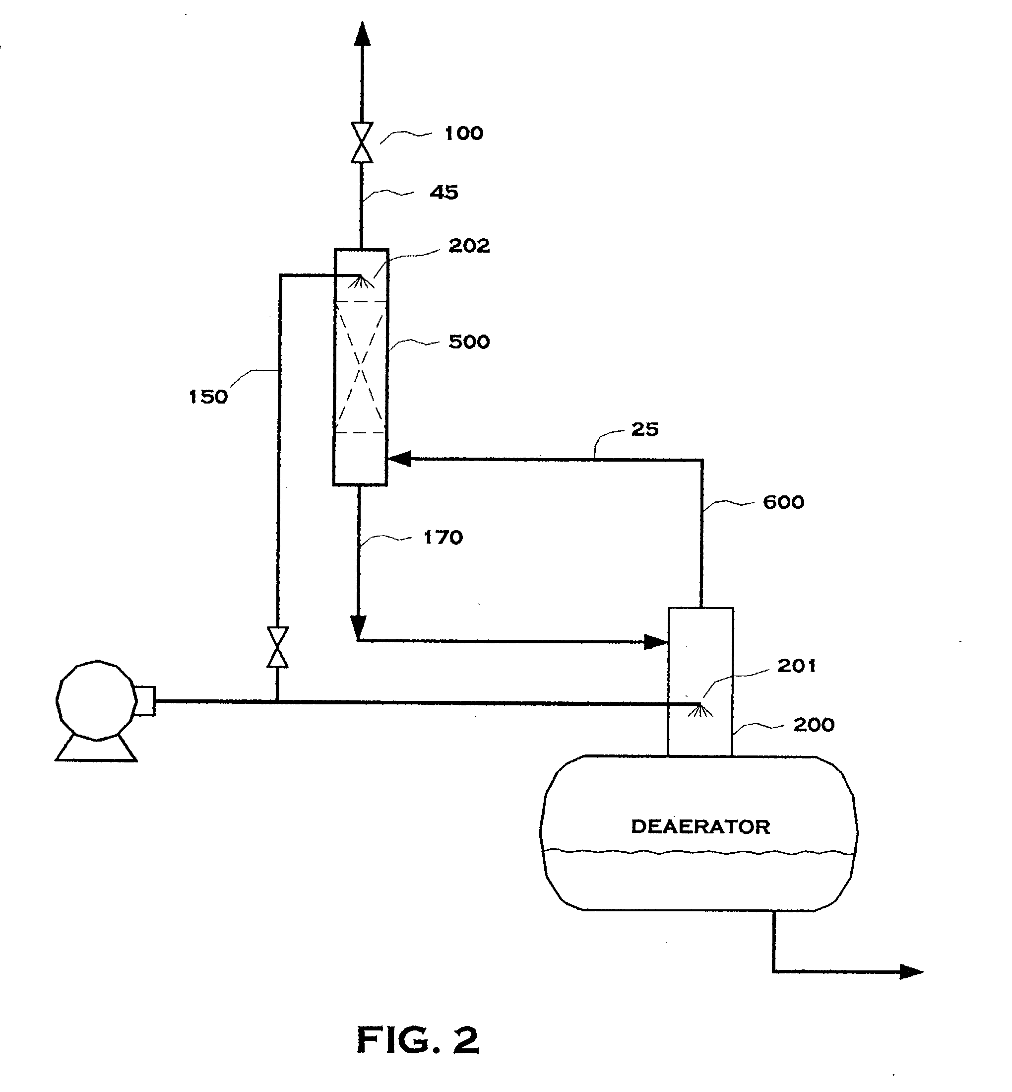
[0038] This invention relates to applying the concept of staged heat and mass transfer (SHMT) to broaden its application. Two groups of applications illustrating the improvements based on the SHMT concept are given. One illustrates commercial applications of recovering vent from steam boiler deaerator systems with enhanced operability, reliability, control robustness and versatility. The other illustrates process adaptations of the SHMT concept to recover steam, steam condensate, and fugitive emissions involving particulate materials if desirable, from any process vent streams.

[0039] Deaerator Steam Vent Application

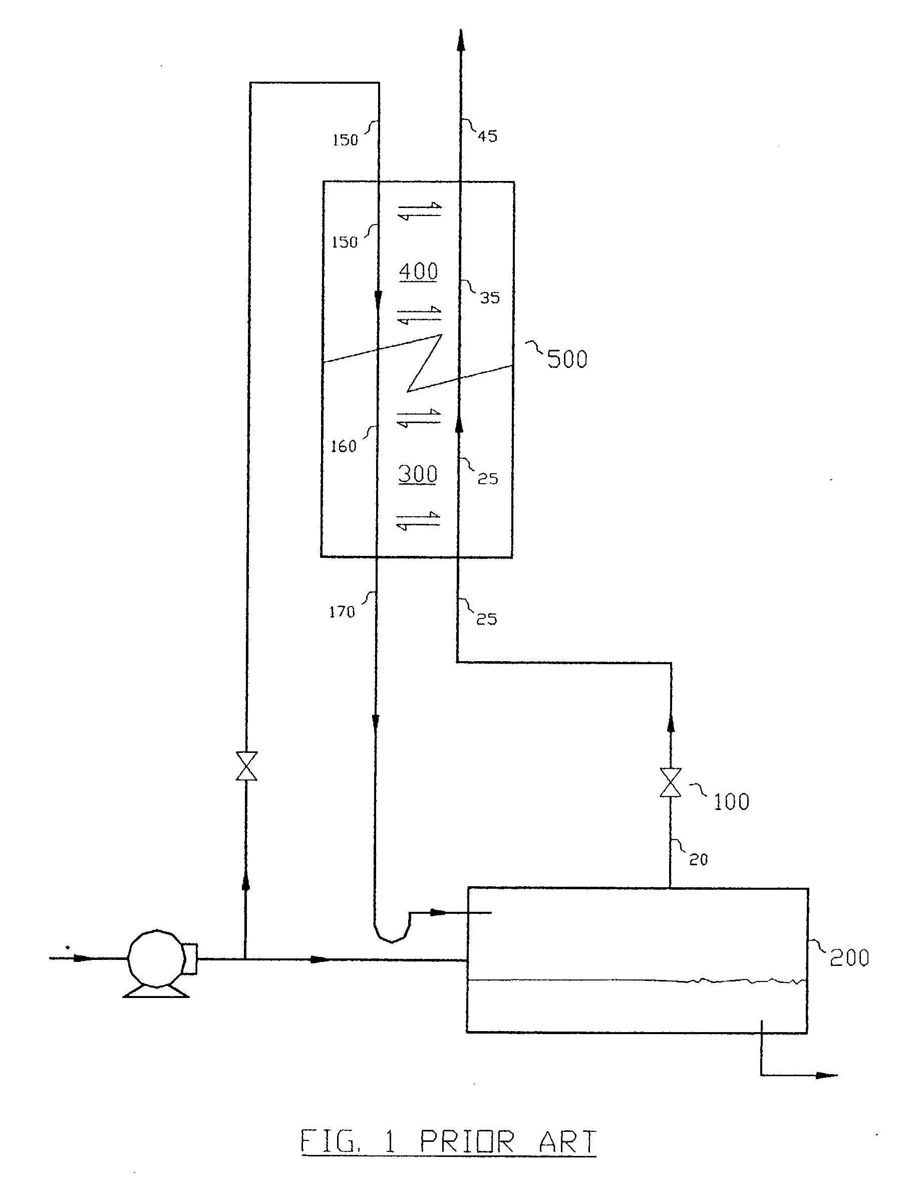
[0040] FIG. 1 shows a deaerator steam vent recovery system with a SHMT unit 500, (U.S. patent application Ser. No. 09 / 536,283) comprised of a heat transfer zone 400 and the mass transfer zone 300, with a movable boundary in between.

[0041] The mass transfer zone 300 allows countercurrent contact of vapor stream 25, which is a steam vent from the deaerator, to strip out dis...


PUM

PropertyMeasurementUnit
pressureaaaaaaaaaa
elevationaaaaaaaaaa
temperatureaaaaaaaaaa

Abstract

This invention exploits the concept of Staged Heat and Mass Transfer (SHMT) to enhance operability, control robustness and intrinsic safety in preventing corrosion while recovering material, and energy if desirable, in process waste streams. Two applications illustrating the improvements based on the SHMT concept are given. One application illustrates novel design features to recover vent from a steam boiler deaeration system, positively eliminating the risk of oxygen and carbon dioxide accumulation in deaerator. The other application illustrates process adaptations of the same SHMT concept to recover steam, steam condensate, and fugitive emissions involving particulate materials if desirable, from any process vents from vessels that are opened to the atmosphere. Again, without the risk of corrosion by atmospheric oxygen.

Description

[0001] 1. Field of Invention[0002] This invention relates generally to processes involving heat and mass transfer applications. In a specific respect, the invention exploits the concept of "Staged Heat and Mass Transfer" (SHMT) as taught in U.S. patent application Ser. No. 09 / 536,283 to enhance operability, control robustness and intrinsic safety in preventing corrosion while recovering material, and energy if desirable, in process waste streams. Two applications illustrating the improvements based on the SHMT concept are given. One illustrates commercial applications of recovering vent from a steam boiler deaeration system. The other illustrates process adaptations to recover steam, steam condensate, and fugitive emissions involving particulate materials if desirable, from any process vents.[0003] 2. Discussion of Prior Art[0004] The concept of SHMT application as explained in U.S. patent application Ser. No. 09 / 536,283 is briefly summarized. A structure comprising a heat transfer ...

Claims


Application Information

Patent Timeline
Patent Type & Authority Applications(United States)
IPC IPC(8): B01D3/14B01D19/00
CPCB01D3/14B01D19/0063B01D19/0047Y02P70/10
Inventor TUNG, PETER
Owner TUNG PETER
Why Eureka
Try Eureka