
Detectable micro to nano sized structures, methods of manufacture and use

a micro- to nano-sized structure and detection method technology, applied in the field of rare earth doped particles mixed, can solve the problems of high cost, high production cost, and difficulty in manufacturing such miniaturized devices, and achieve the effects of improving throughput, simplifying measurement, and simple computer algorithms

Inactive Publication Date: 2004-09-02
CORNING INC
View PDF56 Cites 79 Cited by
  • Summary
  • Abstract
  • Description
  • Claims
  • Application Information

AI Technical Summary

Benefits of technology

The present invention relates to rare earth doped particles and their use as indicators for biological analysis. The particles have unique optical signals that do not interfere with traditional fluorescent dyes, making them ideal for use as identifiers for targets or carriers. The particles can be easily manufactured and used in a wide range of applications, including chemical, biochemical, biological, or biomedical analysis, process control, pollution detection, and security. The indicators and methods of the invention are adaptable to a wide variety of samples and can be used in high throughput drug screening and in vitro immunodiagnostics. The particles have the ability to produce discrete optical signals that do not interfere with traditional fluorescent channels and can be easily detected using conventional optical equipment. The invention does not require new or elaborate methods of illumination or detection.

Problems solved by technology

Although the use of nanoparticles and microparticles offers many advantages, the manufacture of such miniaturized devices has proven difficult.
More specifically, the mass production of such devices in large quantities and at a low cost is particularly problematic.
However, the manufacture of these metallic nanoparticles can be technically challenging and expensive.
In addition, reflectance measurements generally have a high signal to noise ratio and poor sensitivity.
One limitation of the use of fluorescent dyes to identify the particles is that the excitation and emission spectra of these dyes may interfere or overlap with conventional dyes such as Cy3 and Cy3 that are used for labeling reporter molecules used in bioanalysis.
In addition, the fluorescence intensity of dyes tends to deteriorate over time upon prolonged or repeated exposure to light.
Still another limitation of dyes is that the degradation products of these dyes are organic compounds that may interfere with biological processes and molecules being evaluated.
Rare-earth chelates, which are also organic compounds, are also expensive, have low absoption cross-sections, and are not very durable.

Method used


Image

  • Detectable micro to nano sized structures, methods of manufacture and use
  • Detectable micro to nano sized structures, methods of manufacture and use
  • Detectable micro to nano sized structures, methods of manufacture and use

Examples


Embodiment Construction

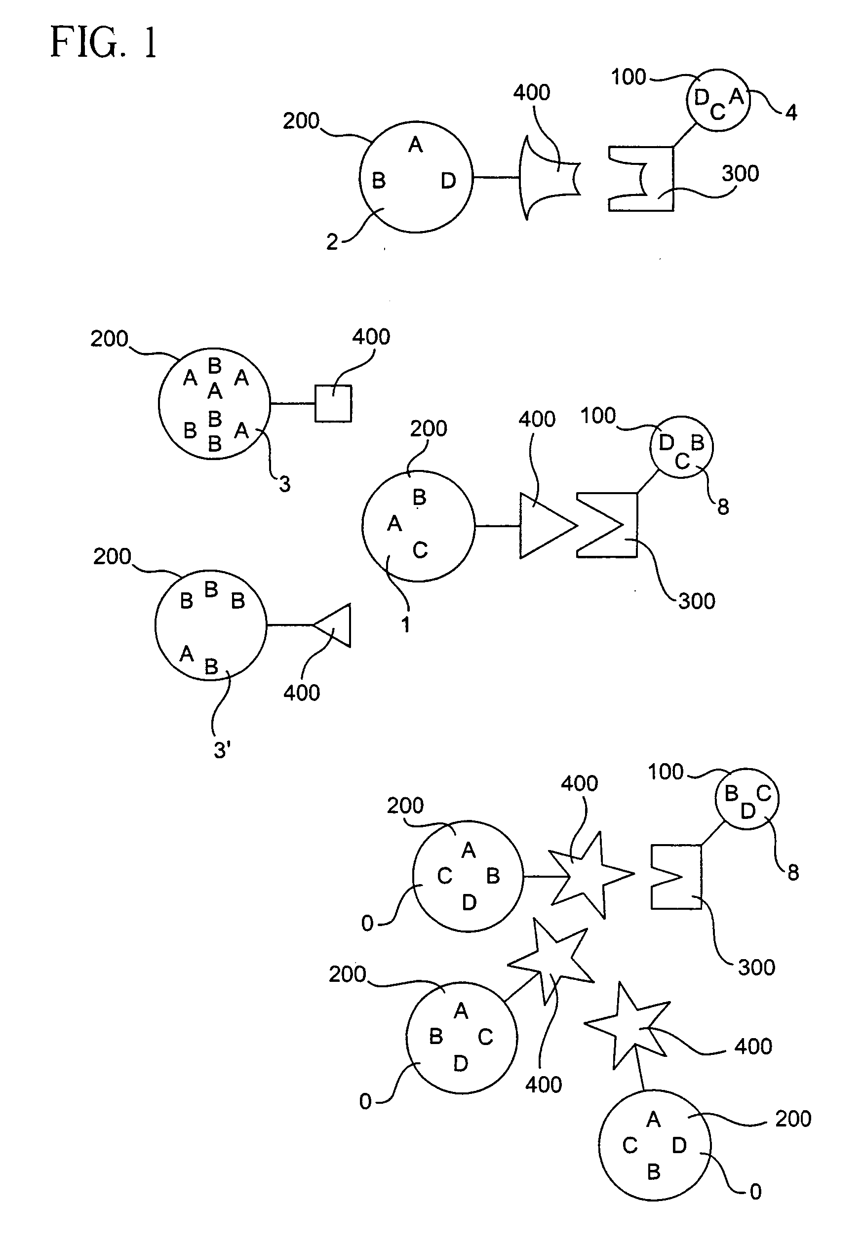
[0044] Tables I and II below show exemplary glass compositions that can be used to make a fluorescent glass particle in accordance with one embodiment of the invention. The glass compositions in Table I and Table II were chosen because fluorescent rare earth materials are soluble in these glasses. It will be understood, however, that the present invention is not limited to a particular glass composition.

1 TABLE I Composition (Weight %) 1 2 3 4 SiO.sub.2 50.61 51.22 52.65 52.40 Al.sub.2O.sub.3 14.56 14.73 15.14 15.07 B.sub.2O.sub.3 7.39 7.49 7.70 7.66 MgO 0.64 0.65 0.67 0.67 CaO 3.65 3.70 3.79 3.78 SrO 1.67 1.69 1.73 1.72 BaO 8.24 8.34 8.57 8.54 Eu.sub.2O.sub.3 6.58 0 0 0 Tb.sub.20.sub.3 0 6.93 0 0 CeO.sub.2 0 0 0.23 0 Tm.sub.2O.sub.3 0 0 0 0.99 Y.sub.2O.sub.3 0 0 4.11 3.79 Sb.sub.2O.sub.3 1.45 0 0 0 F 0.24 0.24 0.24 0.24

[0045]

2 TABLE II Composition (Weight %) 5 6 7 8 SiO.sub.2 55.46 55.31 59.53 59.69 Al.sub.2O.sub.3 0.96 0.95 1.03 1.03 Li.sub.2O 1.60 1.60 1.72 1.72 Na.sub.2O 3.32 3....


PUM

PropertyMeasurementUnit
diameteraaaaaaaaaa
sizeaaaaaaaaaa
sizeaaaaaaaaaa

Abstract

Homogeneously mixed rare-earth doped particles and methods of using such particles include nano to microsized particles having a concentration of at least about 0.0005 mole percent of a Rare-Earth Oxide (Re2O3). The particles can be used for detecting the presence of an analyte in a sample and for detecting interactions of biomolecules.

Description

[0001] This is a continuation-in-part of U.S. patent application Ser. No. 10 / 027,286 filed on Dec. 20, 2001, the content of which is relied upon and incorporated herein by reference in its entirety, and the benefit of priority under 35 U.S.C. .sctn. 120 is hereby claimed.[0002] This invention relates to detectable micro to nano sized structures or particles in general. More particularly, the present invention relates to beads and labels, methods of manufacturing detectable labels and beads and methods of using detectable labels and beads.[0003] Miniaturized markers and indicators have found utility in a wide variety of areas, but they are of particular interest in biological and chemical assays. The development of multiplexing and miniaturization of chemical and biochemical assays has improved the analysis of samples in such areas as biomedical analysis, environmental science, pharmaceutical research, food and water quality control. For example, in the area of genomics, DNA arrays a...

Claims


Application Information

Patent Timeline
Patent Type & Authority Applications(United States)
IPC IPC(8): C40B40/06C40B40/10G01N33/532G01N33/552G01N33/58
CPCB01J2219/00274G01N33/588B01J2219/00509B01J2219/00549B01J2219/00576B01J2219/00585B01J2219/00722B01J2219/00725B82Y15/00C03C3/087C03C3/095C03C3/118C40B40/06C40B40/10G01N33/532G01N33/552G01N33/587B01J2219/005
Inventor DEJNEKA, MATTHEW J.LAHARI, JOYDEEP
Owner CORNING INC
Learn More