Nonreducing dielectric ceramic, its production method and multilayer ceramic capacitor

Inactive Publication Date: 2004-09-09
MURATA MFG CO LTD
View PDF8 Cites 12 Cited by
  • Summary
  • Abstract
  • Description
  • Claims
  • Application Information

AI Technical Summary

Problems solved by technology

This makes it difficult to reduce the price and increase the capacitance of the monolithic ceramic capacitor.
Unfortunately, these base metals used as a conductive material of the internal electrodes are undesirably oxidized by firing under a high oxygen partial pressure.
Unfortunately, the relative dielectric constant of the strontium titanate-based nonreducing dielectric ceramic disclosed in Japanese Unexamined Patent Application Publication No. 2000-53466 is as low as less than 150.
As for the strontium titanate-based nonreducing dielectric ceramic discl

Method used


Image

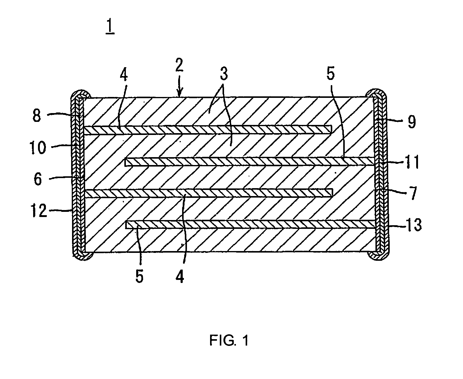
  • Nonreducing dielectric ceramic, its production method and multilayer ceramic capacitor
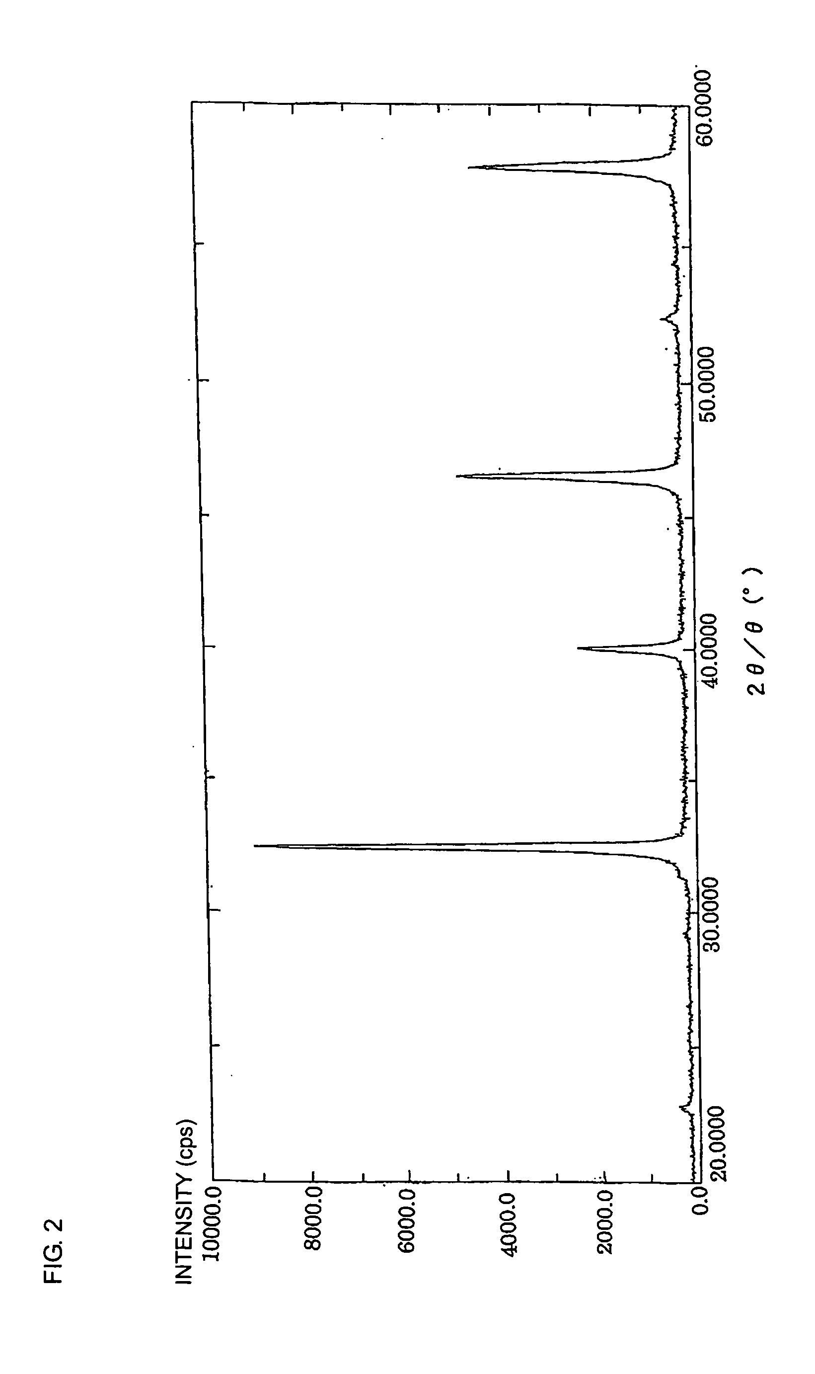
  • Nonreducing dielectric ceramic, its production method and multilayer ceramic capacitor
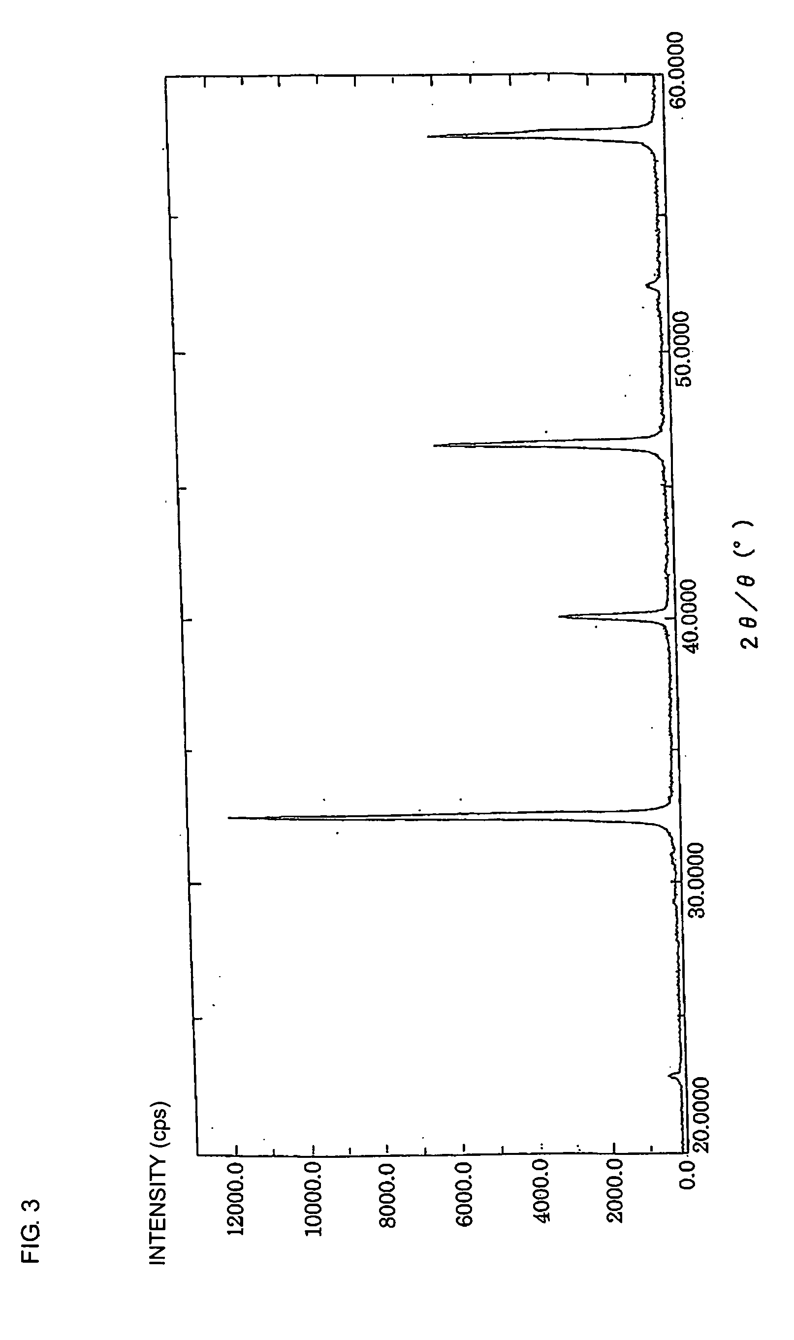
  • Nonreducing dielectric ceramic, its production method and multilayer ceramic capacitor

Examples


experimental example 2

[0121] Prepared were SrCO.sub.3, CaCO.sub.3, BaCO.sub.3, ZrO.sub.2, TiO.sub.2 and HfO.sub.2 powders with purities of 99% or more as the starting powder materials for the principal constituents, as in Experimental Example 1. Oxide powders of Dy, Ho, Er, Tm, Yb, Lu, Y, and Sc were prepared as a starting material for accessory constituent 1. Also, NiO, MnCO.sub.3, and COCO.sub.3 powders were prepared as a starting powder material for accessory constituent 2, as in the accessory constituents in Experimental Example 1.

[0122] The starting powder materials for the principal constituents were weighed out so as to constitute the composition expressed by the formula

(Sr.sub.1-w-xCa.sub.wBa.sub.x).sub.m(Ti.sub.1-y-zZr.sub.yHf.sub.z)O.sub.3,

[0123] according to the values of w, x, y, z, and m shown in Table 4. Also, the starting powder materials for accessory constituents 1 and 2 were weighed out so that their mole numbers became the values shown in Table 4 relative to 100 moles of the principal ...

experimental example 3

[0150] SrCO.sub.3, CaCO.sub.3, and TiO.sub.2 powders with purities of 99% or more were prepared as the starting powder materials for the principal constituents. Also, Yb.sub.2O.sub.3, MnO, Al.sub.2O.sub.3, and MgCO.sub.3 powders were prepared as the starting powder materials for the accessory constituents. These starting powder materials were each weighed out so that the principal constituents form the composition (Sr.sub.0.6Ca.sub.0.4)TiO.sub.3 and that the mole numbers of the accessory constituents in terms of YbO.sub.3 / 2, MnO, AlO.sub.3 / 2, or MgCO.sub.3 became the values shown in Table 7 relative to 100 moles of the principal constituents. The weighed starting powder materials were wet-mixed to prepare an uncalcined powder mixture in the same manner as in Experimental Example 1.

7TABLE 7 Sample YbO.sub.3 / 2 MnO AlO.sub.3 / 2 MgCO.sub.3 number (mol) (mol) (mol) (mol) 58 3.0 2.0 -- --59 3.0 0.5 2.5 --60 3.0 1.0 4.0 --61 3.0 2.0 5.5 --62 3.0 0.5 -- 1.5 63 3.0 1.0 -- 2.5 64 3.0 2.0 -- 4....

experimental example 4

[0161] Prepared were SrCO.sub.3, CaCO.sub.3, ZrO.sub.2, and TiO.sub.2 powders with purities of 99% or more as the starting powder materials for the principal constituents. Also, Yb.sub.2O.sub.3 and MgCO.sub.3 powders were prepared as the starting powder materials for the accessory constituents.

[0162] These starting powder materials were each weighed out so that the principal constituents form the composition (Sr.sub.0.8Ca.sub.0.2) (Ti.sub.0.8Zr.sub.0.2)O.sub.3 and that the mole numbers of the accessory constituents Yb.sub.2O.sub.3 and MgCO.sub.3 in terms of YbO.sub.3 / 2 or MgCO.sub.3 each became 3.0 moles relative to 100 moles of the principal constituents. The weighed starting powder materials were wet-mixed to prepare an uncalcined powder mixture in the same manner as in Experimental Example 1.

[0163] The uncalcined powder mixture was preliminarily calcined at 800.degree. C. for 2 hours in the air to prepare a preliminarily calcined material.

[0164] After being mixed and pulverized i...


PUM

PropertyMeasurementUnit
Fractionaaaaaaaaaa
Percent by massaaaaaaaaaa

Abstract

A nonreducing dielectric ceramic comprising a (Sr, Ca)(Ti, Zr)O3-based perovskite principal crystal phase containing 55 mole percent or more of SrTiO3 and whose powder CuKalpha X-ray diffraction pattern exhibits a ratio of less than 5% of the maximum peak intensity of the accessory crystal phases being the other crystal phases to the intensity of the maximum peak of the perovskite crystal phase, which is present at 2theta=25° to 35°. This strontium titanate-based nonreducing dielectric ceramic has a high relative dielectric constant of 150 or more, a low third-order harmonic distortion ratio, and an excellent reliability in a high temperature-loading test. Accordingly, it is advantageously used for forming dielectric ceramic layers of a monolithic ceramic capacitor.

Description

[0001] The present invention relates to a strontium titanate-based nonreducing dielectric ceramic, a method for manufacturing the same, and a monolithic ceramic capacitor using the nonreducing dielectric ceramic. In particular, the present invention is intended to increase the relative dielectric constant of the nonreducing dielectric ceramic and to thus enhance the reliability of the monolithic ceramic capacitor.[0002] In general, dielectric ceramic materials are reduced to semiconductors by firing under a low oxygen partial pressure in, for example, a neutral or reducing atmosphere. Accordingly, internal electrodes of a monolithic ceramic capacitor comprising such a dielectric ceramic material have to be formed of a conductive material, such as palladium and platinum, that is not oxidized by firing under a high oxygen partial pressure nor is melted at the sintering temperature of the dielectric ceramic material. This makes it difficult to reduce the price and increase the capacita...

Claims


Application Information

Patent Timeline
IPC IPC(8): C04B35/46C03C8/18C04B35/468C04B35/47C04B35/49H01B3/12H01G4/12
CPCB32B18/00H01G4/1245B32B2311/22B82Y30/00C03C8/18C04B35/4682C04B35/47C04B35/49C04B35/6262C04B35/6303C04B2235/3205C04B2235/3206C04B2235/3208C04B2235/3213C04B2235/3215C04B2235/3217C04B2235/3224C04B2235/3225C04B2235/3236C04B2235/3244C04B2235/3249C04B2235/3262C04B2235/3275C04B2235/3279C04B2235/3409C04B2235/3418C04B2235/36C04B2235/442C04B2235/5445C04B2235/5454C04B2235/6025C04B2235/652C04B2235/6582C04B2235/76C04B2235/762C04B2235/765C04B2235/768C04B2235/96C04B2237/346C04B2237/348C04B2237/405C04B2237/407C04B2237/704H01G4/1227B32B2311/12
Inventor ITO, TOSHIYUKISANO, HARUNOBU
Owner MURATA MFG CO LTD
Why Eureka
Try Eureka