
Liquid-solid circulating fluidized bed waste water treatment system for simultaneous carbon, nitrogen and phosphorus removal

a waste water treatment system and liquid-solid circulating technology, applied in water/sewage multi-stage treatment, filtration separation, separation processes, etc., can solve problems such as anaerobic conditions

Inactive Publication Date: 2004-09-16
UNIV OF WESTERN ONTARIO
View PDF3 Cites 47 Cited by
  • Summary
  • Abstract
  • Description
  • Claims
  • Application Information

AI Technical Summary

Benefits of technology

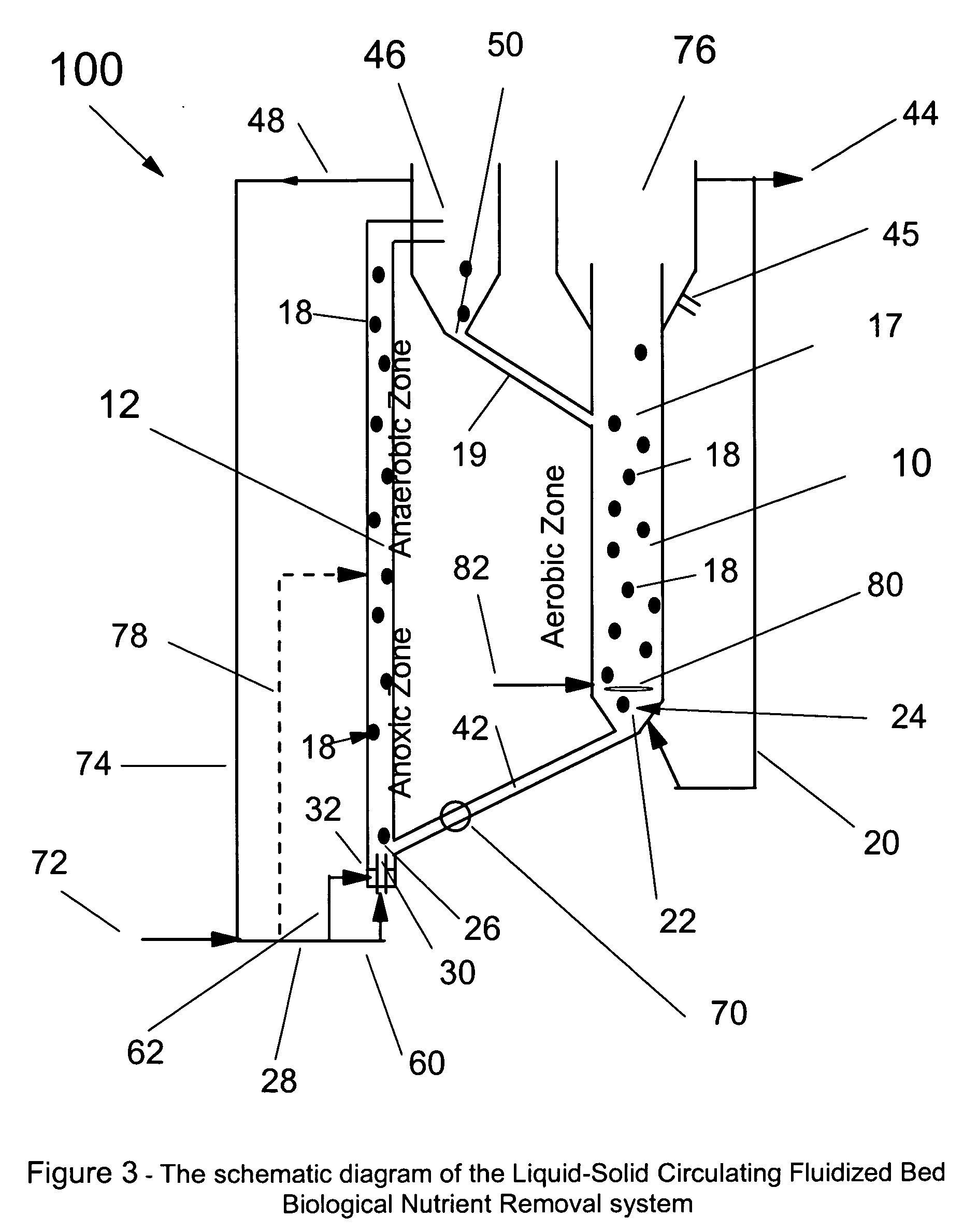
[0014] The BNR-LSCFB system has two fluidized beds interconnected to form a solids circulation system: the riser fluidized bed where both liquid and particles move co-currently upwards and the downer fluidized bed where the liquid and air flows upwards in counter-current with the downflow particles. In the above instance, the riser is a liquid-solid fluidized bed, while the downer is a gas-liquid-solid fluidized bed). LSCFB (including GLSCFB) is a relatively new type of (bio-) chemical processor, which has only been studied recently [7, 8, 9, 10, 11, 12, 13]. The BNR-LSCFB system has been recently developed for wastewater treatment by the inventors to establish a novel fixed-film BNR process. Although LSCFB offers many distinct advantages for many chemical and bioprocesses such as better interfacial contacting and reduced backmixing, it has not been applied in any wastewater treatment processes including the BNR processes. An additional benefit of LSCFB is that it has two separate fluidized beds where two separate processes such aerobic and anoxic processes, can be accommodated in the same system.
[0051] 9) the potential reduction in organic carbon requirements for nutrient-removal due to enhanced utilization of particulate substrates as a result of better entrapment in the fluidized bed as well as decaying biofilm as a carbon source.

Problems solved by technology

Since this demand is not met due to lack of oxygen / air inflow, anaerobic conditions prevail.

Method used


Image

  • Liquid-solid circulating fluidized bed waste water treatment system for simultaneous carbon, nitrogen and phosphorus removal
  • Liquid-solid circulating fluidized bed waste water treatment system for simultaneous carbon, nitrogen and phosphorus removal
  • Liquid-solid circulating fluidized bed waste water treatment system for simultaneous carbon, nitrogen and phosphorus removal

Examples


Embodiment Construction

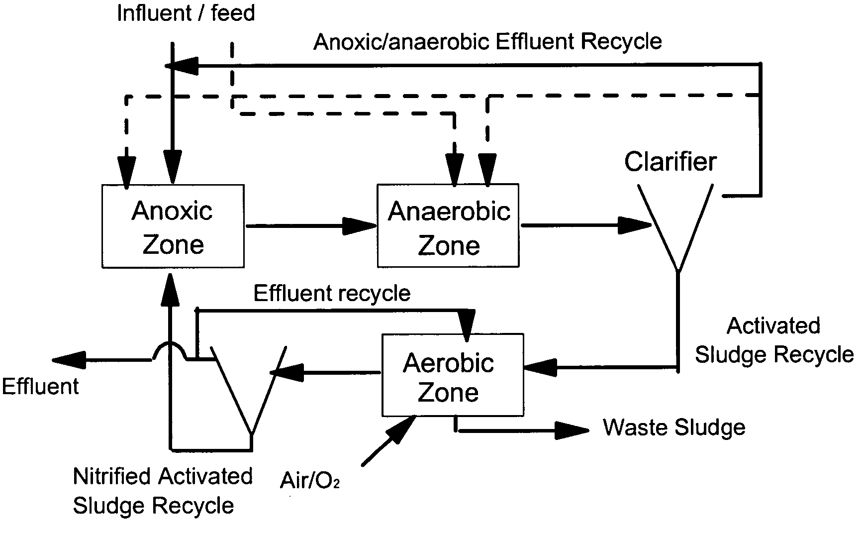
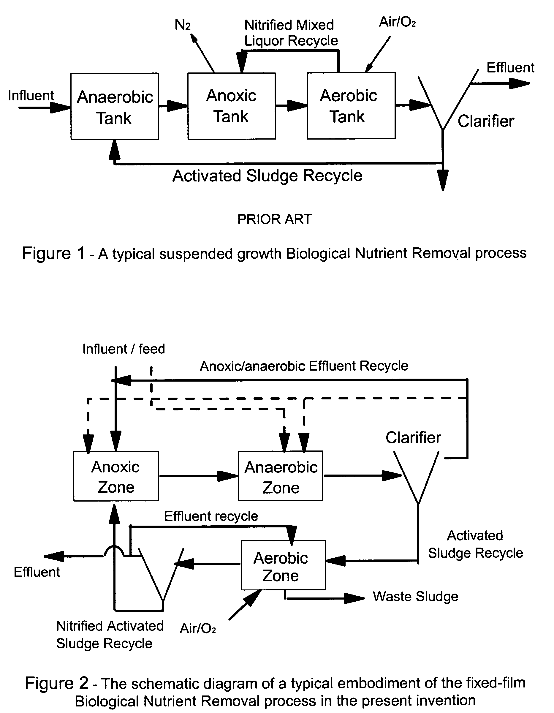
[0039] A flow diagram illustrating the fixed-film BNR process used in the LSCFB 100 (FIG. 3) of the present invention is illustrated in FIG. 2. In connection with FIG. 3, the aerobic process takes place in the downer bed 10 and the anoxic process takes place in the lower part of the riser bed 12 and the anaerobic process takes place in the upper part of the riser bed 12. An alternative is to have the anoxic process in the upper part of the riser and the anaerobic in the lower part of the riser. In this case, however, most of the nitrified effluent from the aerobic zone needs to be fed half way in the riser to the bottom of the anoxic zone. Raw wastewater 72 (primary influent or primary effluent) is first mixed with the anoxic / anaerobic effluent recycle stream 74 from the liquid-solid separator 46 at the top of the riser and then fed into the bottom of the riser bed 12 where the activated sludge loaded on the recirculating solid particles along with some previously nitrified wastewat...


PUM

PropertyMeasurementUnit
Electrical conductanceaaaaaaaaaa
Gravityaaaaaaaaaa
Mass transfer coefficientaaaaaaaaaa

Abstract

Biological nutrient removal (BNR) in municipal wastewater treatment to remove carbonaceous substrates, nutrients and phosphorus, has recently become increasingly popular worldwide due to increasingly stringent regulations. Biological fluidized bed (BFB) technology, which could be potentially used for BNR processes, can provide some advantages such as high efficiency and compact structure. This present invention incorporates the fixed-film biological fluidized bed technology with the biological nutrient removal in a liquid-solid circulating fluidized bed, which has achieved the simultaneous elimination of organic carbon, nitrogen and phosphorus, in a very efficient manner and with very compact space requirements. The BNR-LSCFB has two fluidized beds, running as anoxic / anaerobic and aerobic processes to accomplish simultaneous nitrification and denitrification and to remove carbonaceous substrates, nutrients and phosphorus, with continuous liquid and solids recirculation through the anoxic / anaerobic bed and the aerobic bed. The new BNR-LSCFB system is not only an excellent alternative for conventional activated sludge type BNR technologies but is also capable of processing much higher loadings and suitable for industrial applications.

Description

CROSS REFERENCE TO RELATED U.S. APPLICATIONS[0001] This patent application is a continuation-in-part application of U.S. patent application Ser. No. 09 / 676,453 filed on Oct. 2, 2000, which has now been allowed and which is incorporated herein by reference in its entirety.[0002] The present invention relates to a fluidized bed, and more particularly the present invention relates to a liquid-solid and gas-liquid-solid circulating fluidized bed arrangement specially suited for wastewater treatment and the simultaneous removal of carbon, nitrogen and phosphorus.[0003] Fluidization technology has been developed for close to one century from its first application to coal gasification by Winkler in the 1920s [1]. Since then, fluidized beds have been used for many different applications such as gas-liquid, liquid-solid, and gas-liquid-solid contactors and to carry out a variety of different processes as chemical and biological reactors.[0004] The application of fluidized beds to the biologi...

Claims


Application Information

Patent Timeline
IPC IPC(8): B01D15/02B01D15/04B01D15/18B01D24/00B01D24/36B01J47/10B01J49/00C02F1/00C02F1/42C02F3/00C02F3/08C02F3/12C02F3/30
CPCB01D15/1807B01D2215/021B01J47/10B01J49/0026Y10S210/906C02F3/104C02F3/30C02F3/308Y10S210/903C02F3/085B01J49/10Y02W10/10
Inventor NAKHLA, GEORGEZHU, JINGXUCUI, YUBO
Owner UNIV OF WESTERN ONTARIO
Learn More