
Free space optical communications link tolerant of atmospheric interference

a technology of optical communication and atmospheric interference, which is applied in the direction of electromagnetic transmission, electrical equipment, transmission, etc., can solve the problems of inability to easily use systems of common wavelengths in shared space, radio signals from more than one system using radio waves are intrinsically rather omni-directional, and can not be easily used by more than one system using the same space. , to achieve the effect of high reliability and high resistance to failur

Inactive Publication Date: 2004-10-21
PLANTE JAMES
View PDF28 Cites 148 Cited by
  • Summary
  • Abstract
  • Description
  • Claims
  • Application Information

AI Technical Summary

Benefits of technology

0016] Comes now, James Plante with inventions of free space optical communications systems highly tolerant of atmospheric interference including both devices and methods. It is a primary function of these inventions to provide highly reliable communication systems operating in environments comprised of u...

Problems solved by technology

However, systems using radio waves are intrinsically rather omni-directional.
Radio signals from more than one system sharing the same space tend to interfere with other systems.
Although data transmission links are arranged in radio spectral bands, systems of common wavelength cannot be easily used in shared space.
Accordingly, radio spectrum cannot be freely used.
Microwave systems have signals which tend to be rugged against path interruption.
Microwave systems also suffer from regulatory issues and technical complexities which make their widespread use not possible.
Optical systems tend to require equipment of very high precision and finesse, thus these systems are generally very expensive.
Optical beam systems present great problems for links within Earth's atmosphere.
A first major problem relates to the fact that water vapor contained in the atmosphere tends to absorb energy in the optical beam thereby extinguishing it.
Some IR semiconductor lasers are inexpensive and their use is highly unregulated.
Although the future of FSO systems is quite promising, it is not without serious problems and limitations.
Energy at these wavelengths is highly susceptible to attenuation by scattering from water particles and vapor in the atmosphere among other problems.
In particular, FSO systems based on near infrared wavelengths fail in fog.
Even light fog has a strong adverse effect on optical communications links of 1.55 micron.
In heavy fog, the beam of a 20 meter link is completely extinguished and the link fails entirely.
Because attenuation is severe, even the higher power lasers sure to come in the future will not sufficiently overcome the problem.
Consequently, the bandwidth of such systems is greatly consumed with repeated transmission of the same message between the plurality of nodes.
Further, these mesh architectures require a great deal of equipment be deployed and maintained on regular intervals.
This presents a very complex problem in environments such as a busy city business district.
However, these redundant systems are expensive as they require considerable amounts of additional hardware.
They are also difficult to implement in consideration of the required licenses for radio spectrum.
Also, as mentioned, these systems tend to be omni-directional and interfere with similar links nearby.
They additionally have serious security problems as it is quite easy for other to receive radio signals not intended to be shared.
These systems may include links of considerable length, however, they only remain operative during times of clear weather.
Where a high quality of service is demanded along with a link of great distance, there has heretofore been no solution.
Military applications tend not to be arranged around limited budgets and other constraints found in civilian applications.

Method used


Image

  • Free space optical communications link tolerant of atmospheric interference
  • Free space optical communications link tolerant of atmospheric interference
  • Free space optical communications link tolerant of atmospheric interference

Examples


Embodiment Construction

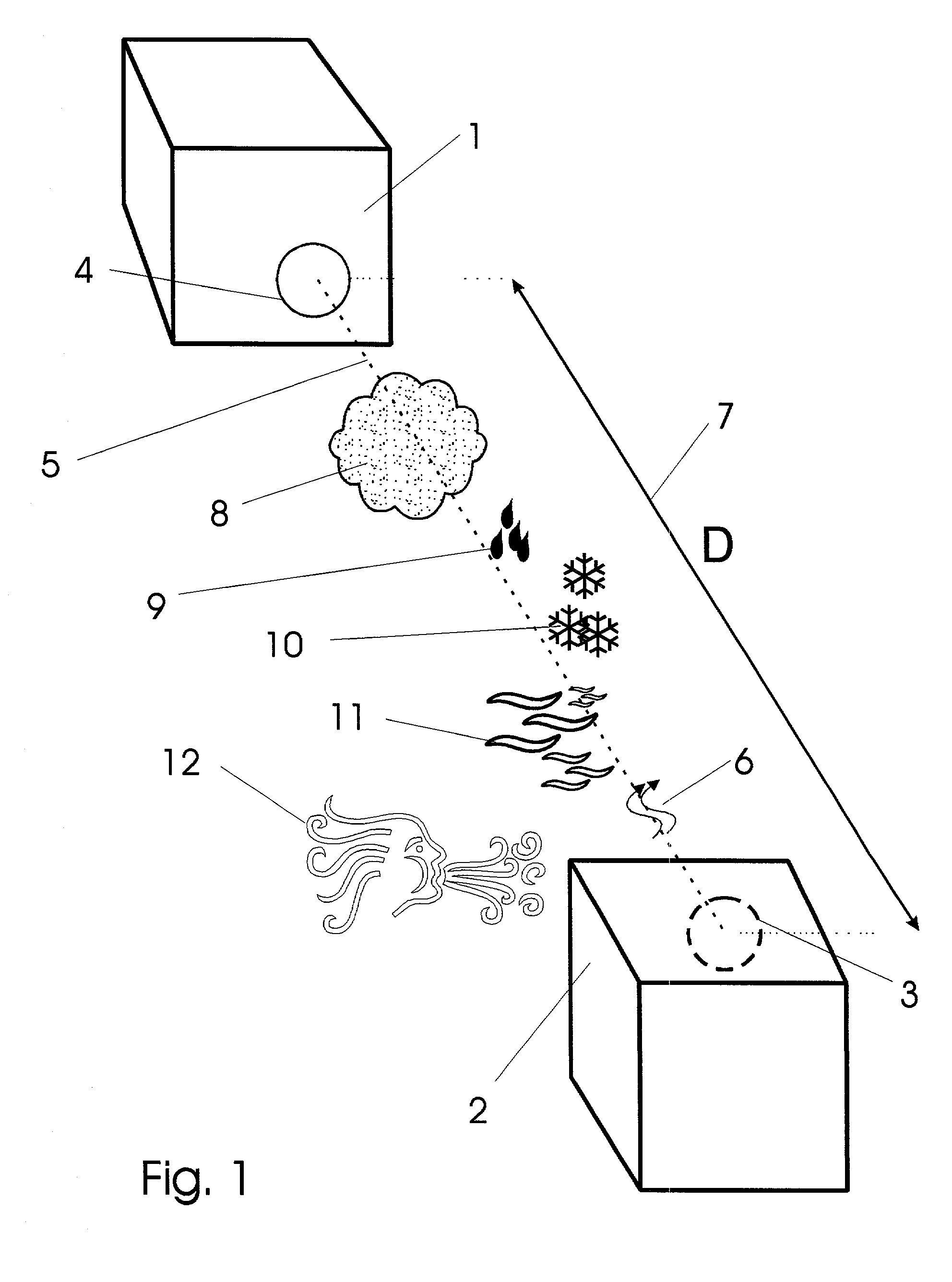
[0066] One will gain a firm and complete appreciation for details of the invention in consideration of drawing figures appended hereto and following descriptions of those figures. With regard to drawing FIG. 1 which is a generalized perspective block diagram showing major elements of a free space optical communications link highly resistant to interruption by atmospheric components. In particular, a first transceiver 1 is in communication with a second transceiver 2 by way of their optical ports or apertures 3 and 4. More precisely, a free space path along an optical axis 5 accommodates propagation of optical radiation 6 in the form of a light beam generated at either of the transceivers. The path is preferably cylindrical and some preferred versions have circular cross section. The free space path has a discrete length `D` indicated in the figure by numeral 7. Further, the free space path may contain therein components unfriendly to the propagation of optical beams such as fog and ...


PUM


Abstract

Free space optical communications systems which resist atmospheric attenuation of optical beams is presented. Very long link distances remain highly reliable despite fog and other inclement weather conditions which otherwise tend to hamper optical transmissions in an atmospheric air column. Systems include primary elements as follows: a plurality of transceivers and at least one air column optical path. Each transceiver includes specialized light sources which produce radiation in the Mid-IR spectral region. In addition, these sources are very compact and well organized in view of their intended deployment environment. Further, special modulation means are joined with particular light sources to address high bandwith needs. In addition, specialized detection strategies are presented whereby sensitivity is improved. Alternative versions and configurations directed to specialized function are also described in detail.

Description

[0001] 1. Field[0002] The field of these inventions described herefollowing may be best characterized as wireless communications links and more specifically Mid-IR free space optical communications links for conveyance of information.[0003] 2. Prior Art[0004] Wireless links arranged for the conveyance of information signals are becoming commonplace due to new demands of digital information consumers. Indeed, Internet traffic and other digital media activity has recently shifted great attention to the development of very high bandwidth wireless networks for transmission of data.[0005] A first important type of wireless link is used in networks common to mobile telephone systems. A network of radio transceivers provides connectivity services to users who may be moving about a coverage region; i.e. within range of radio transceivers. A mobile unit includes a radio transceiver which passes information encoded upon a radio carrier signal. Radio frequency radiation freely passes through t...

Claims


Application Information

Patent Timeline
IPC IPC(8): H04B10/10
CPCH04B10/1125
Inventor PLANTE, JAMES
Owner PLANTE JAMES
Learn More