Zinc recovery process

a zinc recovery and zinc technology, applied in the direction of dissolving, inorganic chemistry, zinc compounds, etc., can solve the problems of affecting the electrolysis and purity of zinc produced, silver and mercury are not so readily removed, and the cost of the process is increased

Inactive Publication Date: 2004-12-02
INTEC INT PROJECTS
View PDF11 Cites 45 Cited by
  • Summary
  • Abstract
  • Description
  • Claims
  • Application Information

AI Technical Summary

Problems solved by technology

In addition, if the ore contains high levels of impurities this can adversely affect the electrolysis and purity of zinc produced.
The existing process is constrained in its ability to treat zinc mineral concentrates containing significant manganese, as the manganese leaches into the leachate along with the zinc and cannot be effectively removed.
Manganese causes problems in the zinc electrolytic recovery step by depositing on the anodes as MnO.sub.2.
Many impurities can be removed from the electrolyte solutions of these processes by a stepwise pH adjustment and precipitation (eg. up to around pH 6), however, both silver and mercury are not so readily removed.
The amalgam requires separate production, requiring a physical association with the mercury and copper, and this is cumbersome and complex, adding to the cost of the process.
In addition, the amalgam must then be added to the process and contacted with the silver-bearing electrolyte, increasing the complexity and cost of running the process.
Other ionic species include ionic gold etc which is less economical.

Method used


Image

  • Zinc recovery process
  • Zinc recovery process
  • Zinc recovery process

Examples


example 1

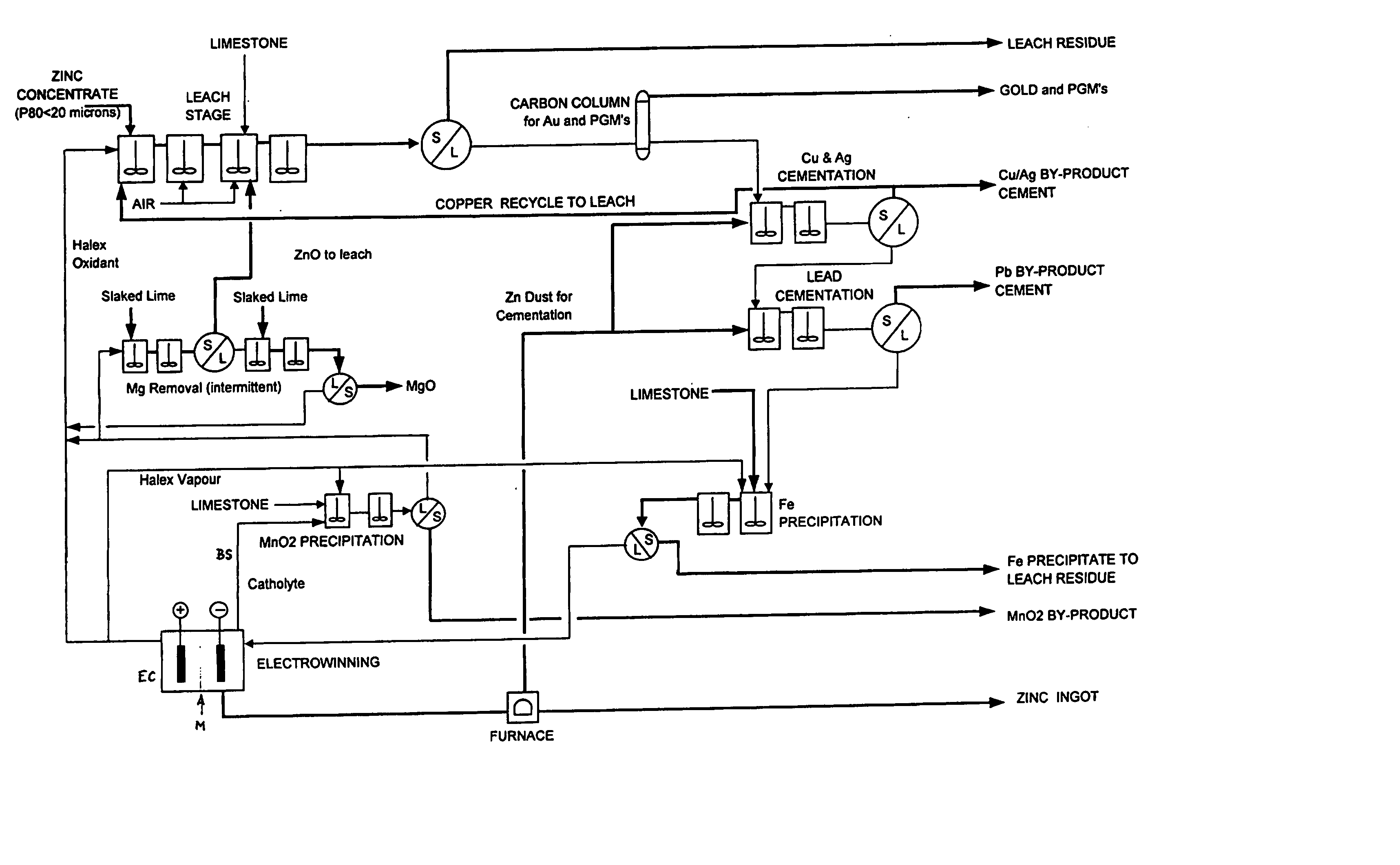
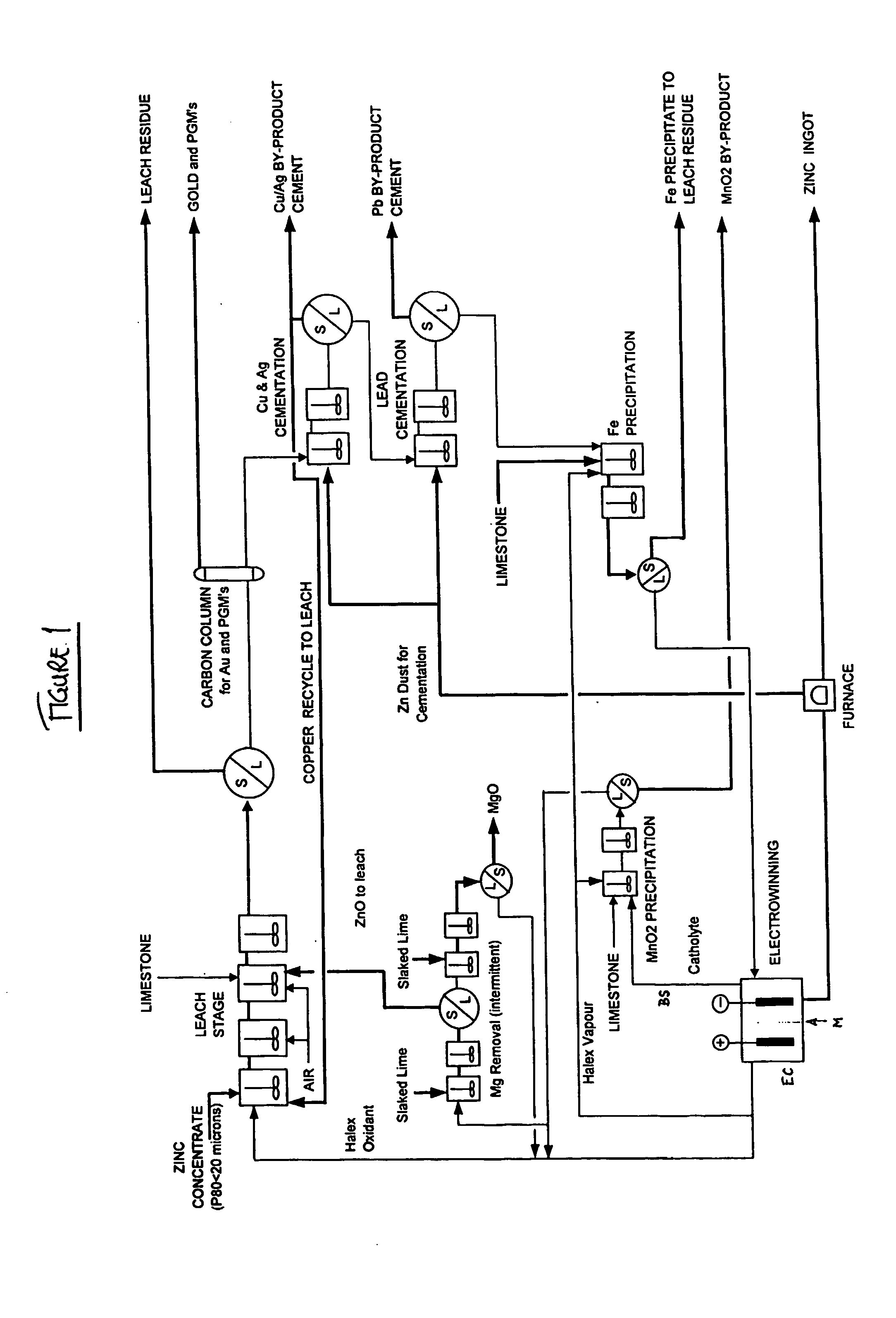
[0107] An electrolyte comprising 200 gpl NaCl, 150 gpl NaBr, 30 gpl Ca.sup.2+, 25 gpl Zn.sup.2+ and 5 gpl Mn.sup.2+ was prepared as a typical bleed stream from a lead / zinc recovery process. 25 gpl CaCO.sub.3 was added to the electrolyte in a reaction vessel at the commencement of the removal process. Ca(OCl).sub.2 was added directly to the electrolyte to oxidise the solution. The temperature of the solution was maintained at a typical process electrolyte temperature of 60.degree. C. to 65.degree. C. The results are shown in Table 1 below.

example 2

[0108] An electrolyte comprising 50 gpl NaCl, 110 gpl NaBr, 50 gpl CaCl.sub.2, 50 gpl Zn.sup.2+ and 15 gpl Mn.sup.2+ was prepared as a typical bleed stream from a lead / zinc recovery process. 85 gpl CaCO.sub.3 was added to the electrolyte in a reaction vessel at the commencement of the removal process. Halex vapours were generated externally and pumped into the reaction vessel. The temperature of the solution was maintained at a typical process electrolyte temperature of 60.degree. C. to 65.degree. C. The results are shown in Table 2 below.

example 3

[0109] An electrolyte comprising 50 gpl NaCl, 110 gpl NaBr, 50 gpl CaCl.sub.2, 50 gpl Zn.sup.2+ and 15 gpl Mn.sup.2+ was prepared as a typical bleed stream from a lead / zinc recovery process. CaCO.sub.3 was added to the electrolyte in a reaction vessel in small doses throughout the removal process. Halex vapours were generated externally and pumped into the reaction vessel. The temperature of the solution was maintained at a typical process electrolyte temperature of 60.degree. C. to 650C. The results are shown in Table 3 below.


PUM

PropertyMeasurementUnit
concentrationaaaaaaaaaa
pHaaaaaaaaaa

Abstract

A process for the recovery of zinc metal from a zinc mineral includes the steps of leaching the zinc mineral in a solution including a halide species formed from two or more different halides, to leach the zinc into the solution. The zinc-bearing solution is then electrolysed to yield zinc metal and to generate the halide species. The electrolysed solution including the halide species is then returned to the leaching step. A portion of the electrolysed solution can be removed as a bleed stream from a cathode compartment of an electrolytic cell of the electrolysis process and processed to remove manganese as manganese dioxide precipitate by adding thereto limestone, and the halide species from an anode compartment of the electrolysis process. In this regard, the pH and Eh of the solution can regulated in a manner that favours the formation of the manganese dioxide precipitate over the formation of a precipitate of zinc.

Description

[0001] The present invention relates to a process for the recovery of zinc from a zinc ore using a halide-based leaching solution. The invention also relates to a method for removing manganese from zinc and other metal halide solutions, and especially zinc and / or lead halide solutions. Further, the invention relates to a method for removing silver and / or mercury from metal halide solutions, especially zinc or cuprous chloride solutions (eg. in a hydrometallurgical process for zinc or copper production).BACKGROUND TO THE INVENTION[0002] An existing process for zinc production involves roasting of a zinc containing ore, followed by acid sulphate leaching and then electrolytic recovery of zinc from the leachate. The roasting process produces sulphur-based pollutant gases which must be removed from the roasting furnace exhaust. In addition, if the ore contains high levels of impurities this can adversely affect the electrolysis and purity of zinc produced. For example, many zinc ores co...

Claims


Application Information

Patent Timeline
Patent Type & Authority Applications(United States)
IPC IPC(8): C22B19/00C22B3/04C22B3/06C22B3/10C22B3/12C22B3/20C22B3/44C22B3/46C22B15/00C22B19/20C25C1/16
CPCC22B3/10C22B19/22C22B19/26C25C1/16Y02P10/20C22B3/04
Inventor MOYES, JOHNHOULLIS, FRANK
Owner INTEC INT PROJECTS
Why Eureka
Try Eureka