Biosensor and method for detecting analytes by means of time-resolved luminescene

Inactive Publication Date: 2004-12-09
MICRONAS
View PDF8 Cites 107 Cited by
  • Summary
  • Abstract
  • Description
  • Claims
  • Application Information

AI Technical Summary

Problems solved by technology

However, the products on the market are relatively expensive because of the large number of system components required together with the high complexity associated therewith, and essentially cannot be miniaturised any further.
The unavoidable result of this is that a wavelength filter is interposed on the biosensor between the surface on which the luminophore is immobilised and the detector in order to mask out the excitation light and to enable the emitted luminescence light t

Method used


Image

  • Biosensor and method for detecting analytes by means of time-resolved luminescene
  • Biosensor and method for detecting analytes by means of time-resolved luminescene
  • Biosensor and method for detecting analytes by means of time-resolved luminescene

Examples


Example

[0100] Manufacture of a Biosensor According to the Invention in the Form of a Microchip

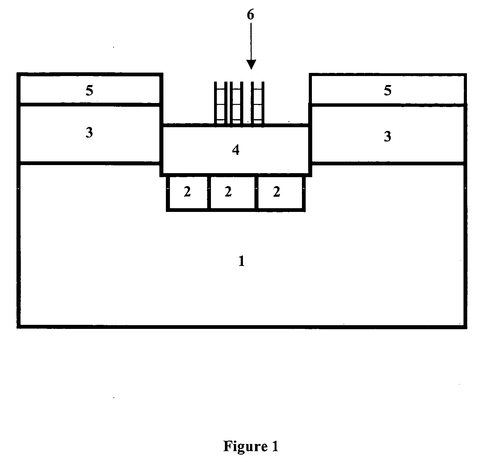
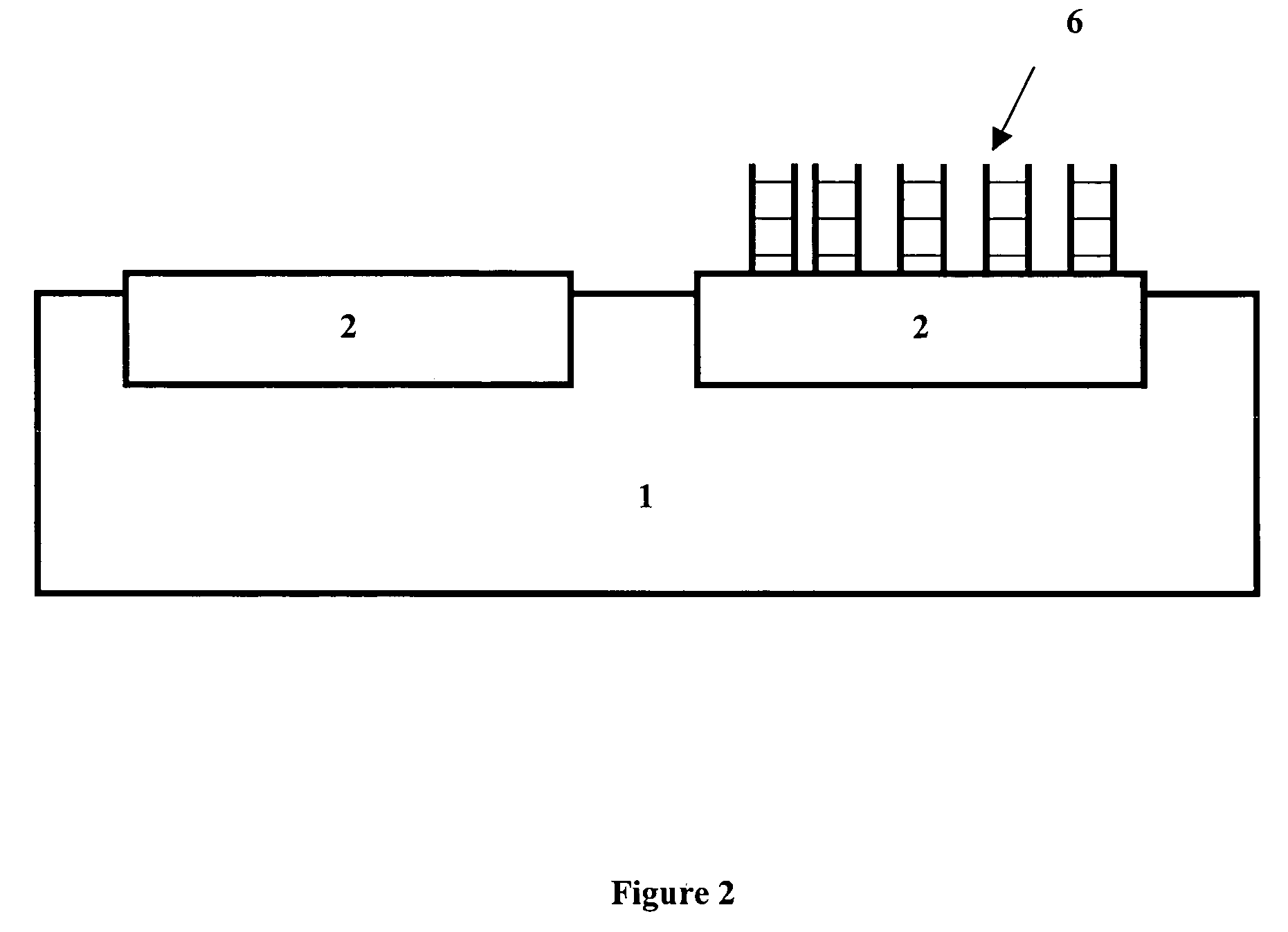
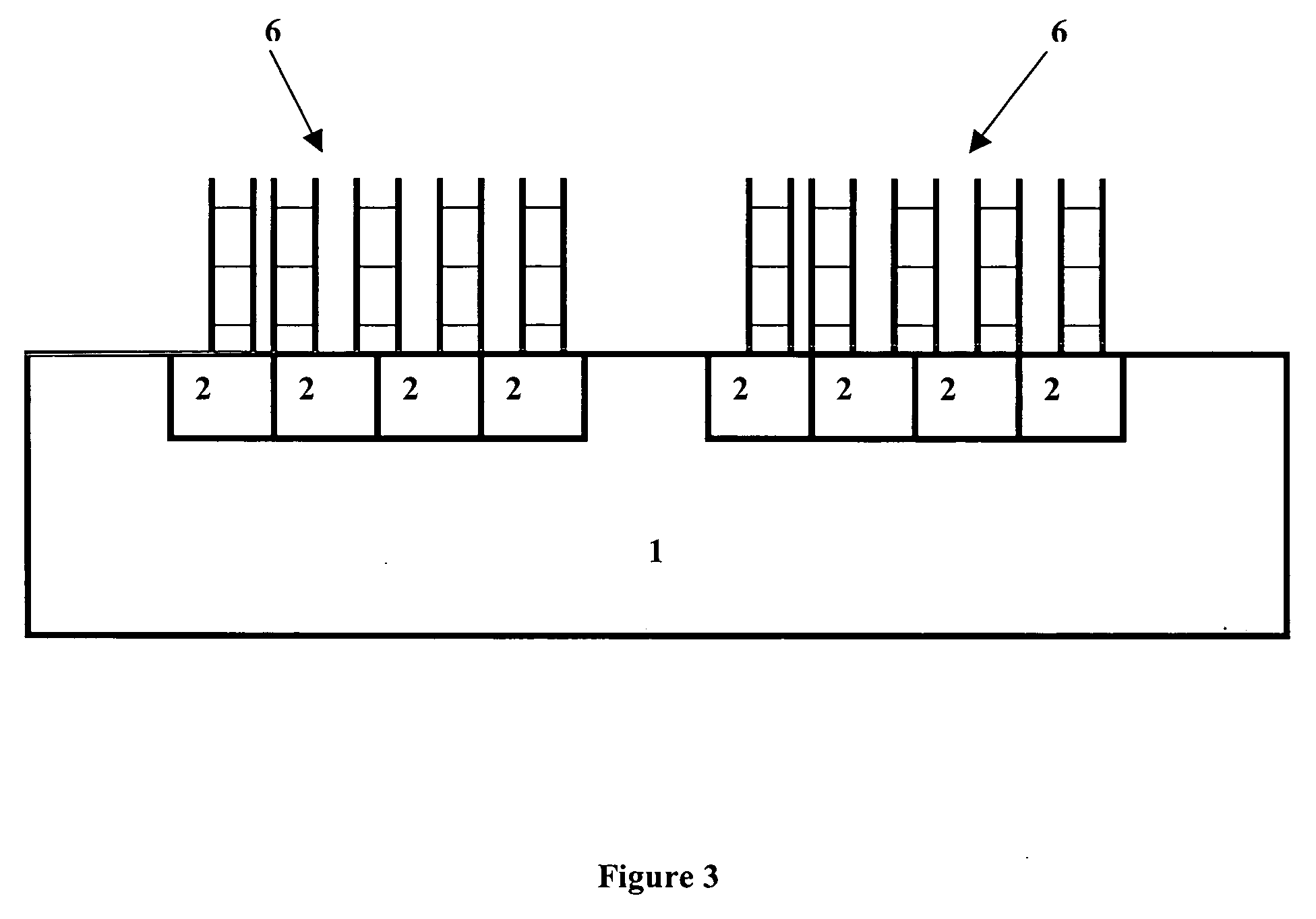
[0101] The sensor is fabricated using 6" (inch) wafers with a 0.5 .mu.m CMOS process. Each pn photodiode is arranged in an n-trough on p-substrate. After the field oxidation, the definition of the p-regions of the photodiode and the application of the 10 nm thick gate oxide layer take place. This is followed by the superimposition and structuring of a silicon dioxide layer. Finally the other usual CMOS steps are performed, such as for example the application of a wiring layer and surface passivation (scratch protection).

[0102] Coating the CMOS Biosensor

[0103] The CMOS sensor manufactured as above is coated with the silane by dipping it into a solution of 1% GOPS (glycidyloxypropyl triethoxysilane) and 0.1% triethylamine in toluene for a period of approx. 2 hours. Afterwards the microchip is removed from the solution and after dripping dry for a short time it is fixed in a drying cabinet at 120.deg...


PUM

PropertyMeasurementUnit
Nanoscale particle sizeaaaaaaaaaa
Sizeaaaaaaaaaa
Sizeaaaaaaaaaa

Abstract

The present invention concerns in general a biosensor in the form of a microchip for the optical detection of analytes and a method using this biosensor. In particular the invention concerns biosensors for detecting an analyte by time-resolved luminescence measurement and a corresponding method.

Description

[0001] The present invention concerns in general a biosensor in the form of a microchip for the optical detection of analytes and a method using this biosensor. In particular the invention concerns biosensors for detecting an analyte by time-resolved luminescence measurement and a corresponding method.THE STATE OF THE ART[0002] The use of essentially planar systems, described among experts as biosensors or biochips, i.e. biosensors in the form of microchips, for the qualitative and / or quantitative detection of the presence of certain substances, e.g. biomolecules, in a sample to be analysed, is already known. These biochips comprise a support on whose surface as a rule there is constructed a plurality of detection fields, for the most part in a matrix arrangement, whereby the individual fields or regions and / or groups of regions each differ from one another in their specificity towards a particular analyte that is to be detected. In the case where DNA analytes are to be detected, sp...

Claims


Application Information

Patent Timeline
IPC IPC(8): C12M1/00C12N15/09C12Q1/68G01N21/64G01N21/76G01N33/53G01N33/543G01N33/566G01N37/00
CPCB01J2219/00529B01J2219/00576B01J2219/00596B01J2219/00608B01J2219/00612B01J2219/00626B01J2219/00637B01J2219/00677B01J2219/00704B82Y30/00G01N21/6408G01N21/6454G01N33/54373G01N33/533G01N33/60G01N33/549
Inventor KLAPPROTH, HOLGERLEHMANN, MIRKO
Owner MICRONAS
Why Eureka
Try Eureka