Actuator driving device of working machine

a technology of working machine and driving device, which is applied in the direction of dynamo-electric converter control, multiple dynamo-motor starters, servomotors, etc., can solve the problems of high manufacturing cost, low manufacturing cost, and limited working space for devices, and achieves a large working area in the working machine, high thrust, and strict space-saving

Inactive Publication Date: 2005-01-06
KOBELCO CONSTR MASCH CO LTD
View PDF2 Cites 34 Cited by
  • Summary
  • Abstract
  • Description
  • Claims
  • Application Information

AI Technical Summary

Benefits of technology

[0012] According to claim 5 of the invention, the working machine is of a self-traveling type, and the power supply is mounted on this working machine. This has the big advantage that, even when mounting the power supply on the self-traveling machine with its weight and a setting space to accommodate devices strictly limited, an area for working in the working machine is enlarged.
[0013] According to claim 6 of the invention, at least one of the electric motors drives the hydraulic pump, which drives at least one of the actuators. This makes it possible to work with high thrust and high torque using the actuator.
[0014] According to claim 7 of the invention, the hydraulic pump is in the form of variable capacity, and the controller controls the power generated by the motors by restricting a revolving speed of each of the electric motors in accordance with output torque of the electric motors, while controlling driving torque of the hydraulic pump by reducing an amount of discharge from the hydraulic pump with respect to discharge pressure of the hydraulic pump so that the po

Problems solved by technology

Thus, when a prescribed work is intended to be carried out by the motor-operated actuator device, the electric motor should have a larger size, and its power supply capacity be increased, leading to higher manufacturing costs.
Then, downsizing of the electric motor or power supply capacity results in low manufacturing costs, but restricts available continuous working time.
However, in cases where the d

Method used


Image

  • Actuator driving device of working machine
  • Actuator driving device of working machine
  • Actuator driving device of working machine

Examples


embodiment 1

[0029] (a) Embodiment 1

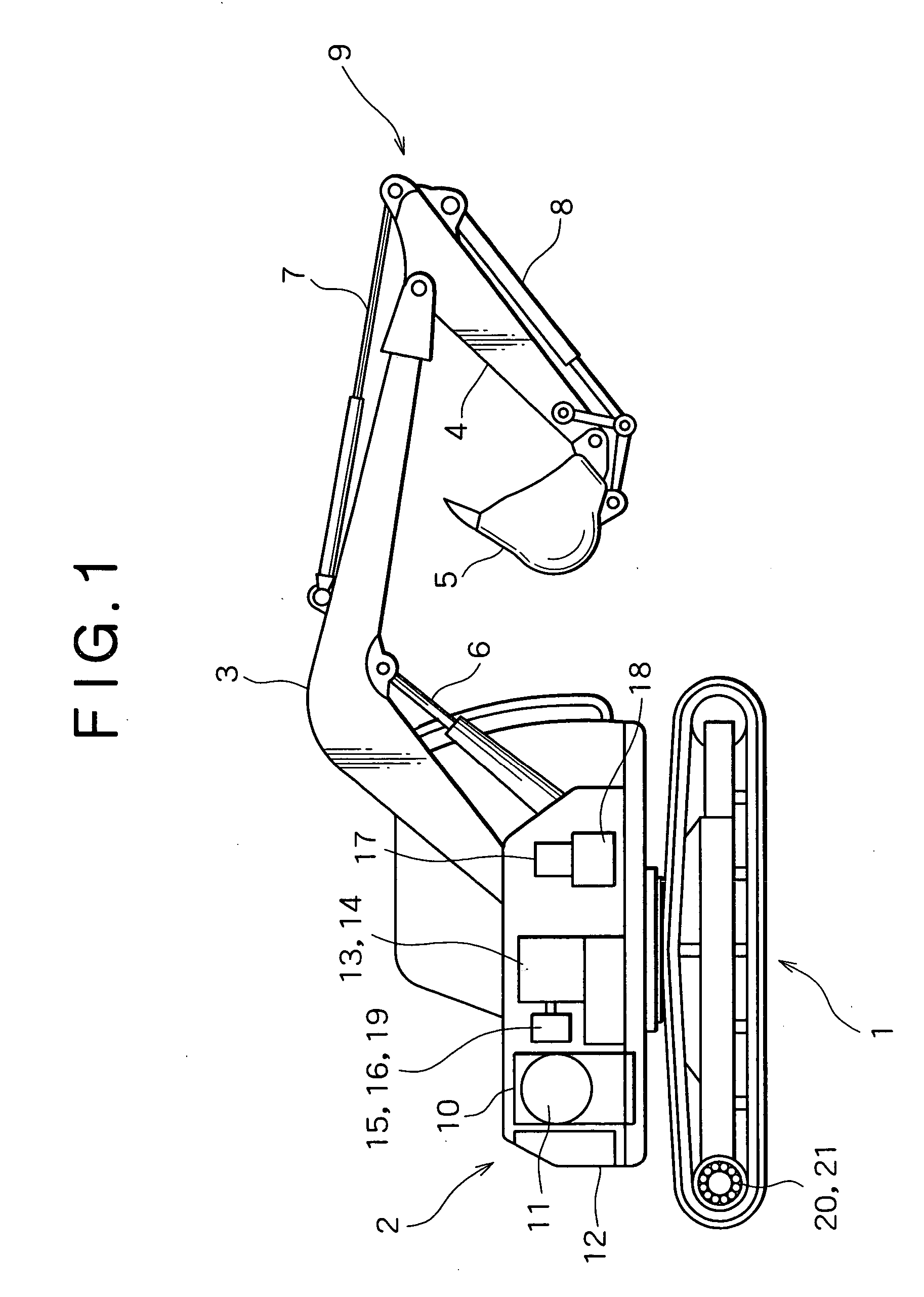
[0030]FIG. 1 shows the entire configuration of a hydraulic excavator. In the figure, on a crawler type lower traveling body 1 is rotatably mounted an upper traveling body 2. In front of the upper rotating body 2 is mounted an excavating attachment 9 which includes a boom 3, an arm 4, a bucket 5, a boom cylinder for boom rising / falling 6, an arm cylinder for arm operating 7, and a bucket cylinder for bucket operating 8.

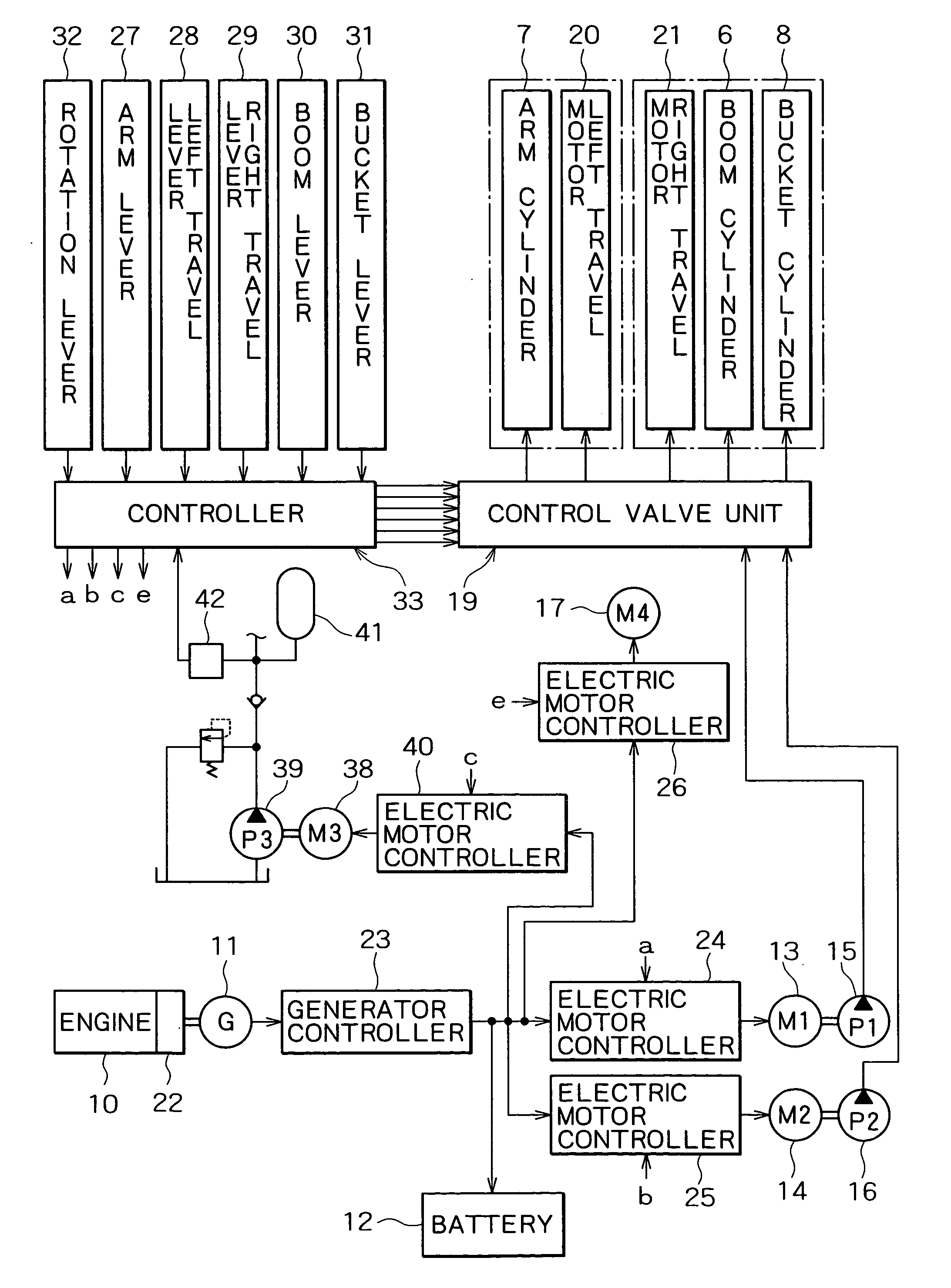
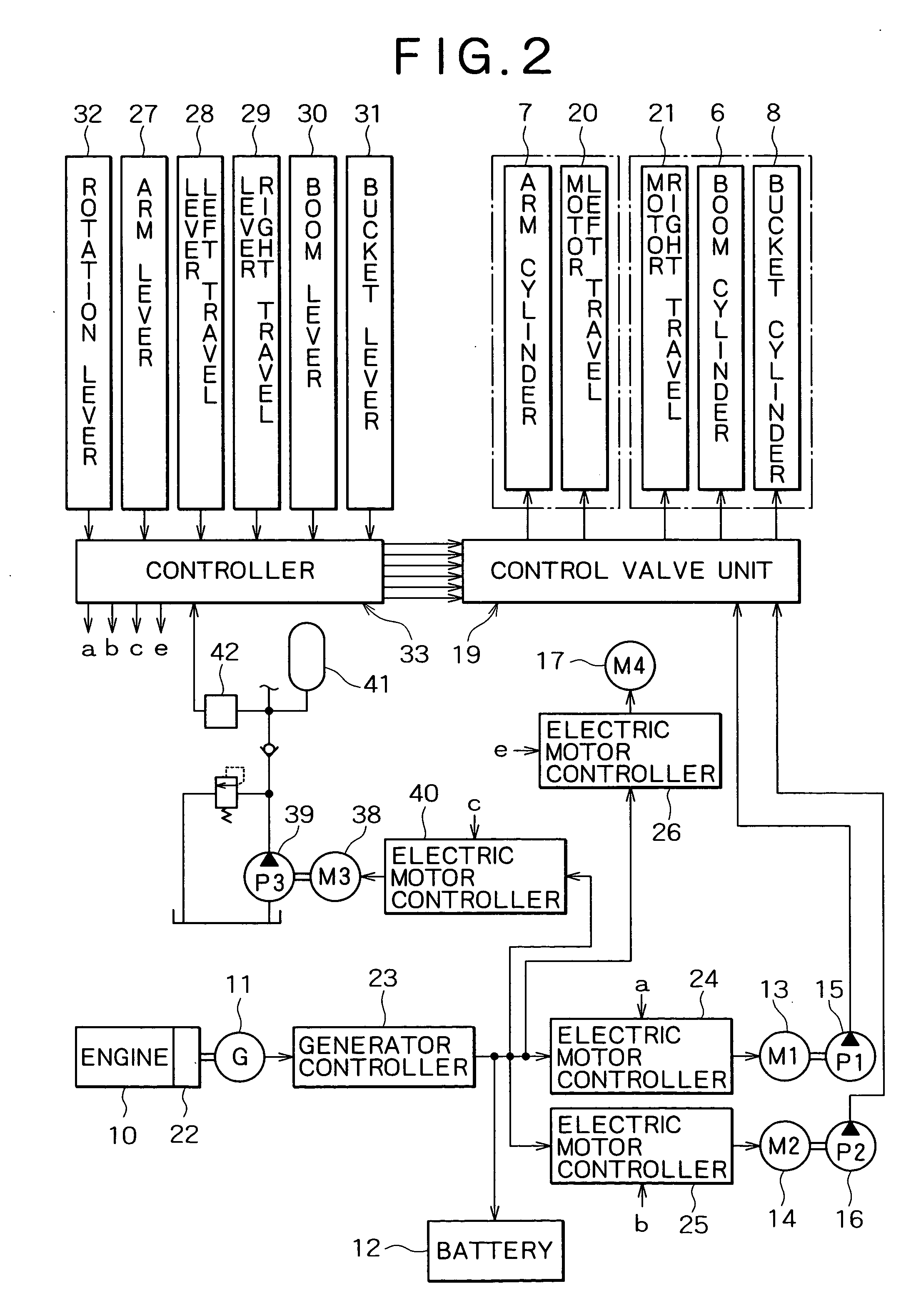
[0031] In the upper rotating body 2 are disposed an engine 10 as a power source, a power generator 11 driven by this engine 10, a battery 12, two electric motors, i.e., a first electric motor 13 and a second electric motor 14 (one of which is shown in the figure, and which are denoted at M1 and M2 in FIG. 2), and first and second hydraulic pumps 15 and 16 (one of which is shown in the figure, and which are denoted at P1 and P2) individually driven by both electric motors 13 and 14. Further, in the rotating body 2 are disposed an electric motor f...

embodiment 2

[0058] (b) Embodiment 2

[0059]FIG. 8 shows the configuration of driving and control systems of a hydraulic excavator according to the second embodiment of the invention. In the figure, elements that are in common to the first embodiment are given the same reference characters, and thus explanation thereof will be omitted.

[0060] As shown in FIG. 8, a generator-electric-motor 11a and first, second, and third hydraulic pumps 15, 16, and 39 (in the figure, which are denoted at P1, P2, and P3, respectively) are altogether connected to an output shaft of the engine 10. It is noted that a boom and a rotating element are individually driven. That is, a boom cylinder for boom riding / falling 6 is operated by pressure oil supplied from a hydraulic motor for the boom 46a (denoted at OM5) which is driven by an electric motor for the boom 44 (denoted at M5). This pressure oil is supplied from a hydraulic pump for the boom 46 (denoted at P5) driven by the boom electric motor 44. The controller 33 ...

embodiment 3

[0066] (c) Embodiment 3

[0067] The third embodiment is constituted by replacing the pump of the first embodiment with a variable capacity type one. FIG. 10 shows electric motor and pump characteristics of a hydraulic excavator according to the third embodiment.

[0068] As shown in FIGS. 10A and 10B, the first and second electric motors 13 and 14 have the maximum power of 3000 min−1×70 Nm=22 kW as a predetermined rated output. The first and second hydraulic pumps 15 and 16 are controlled to have the following constant values: capacity q of 20 cm3 / rev; a maximum pressure of 30 MPa; and a torque of 70 Nm. The combination of the electric motor and the pump provides a graph indicating a relationship between pressure and flow rate, such as that shown in FIG. 11. By controlling the revolving speeds of the first and second electric motors 13 and 14 by an operator's manipulation, amount of discharge of the first and second pumps 15 and 16 is controlled.

[0069] The first and second hydraulic pu...


PUM


Abstract

A device, mounted on a hydraulic excavator, for allowing each of first and second electric motors (13), (14) to generate power by using electric power supplied from a power supply having a predetermined capacity, and actuating a boom cylinder (6), an arm cylinder (7), etc. using the generated power. The device is characterized by comprising electric motor controllers (24), (25), etc. for respectively controlling power that is generated by the electric motors (13), (14) so that, in machine-operation, powers generated by the electric motors (13), (14) may be equal to or less than predetermined rated outputs, and that the total amount of powers generated simultaneously by the electric motors (13), (14) may correspond to the maximum capacity of the power supply, so as to prolong the time of use with high thrust and high torque without increasing the capacitors of the electric motors (13), (14) and power supply.

Description

TECHNICAL FIELD [0001] The present invention relates to an actuator driving device for actuating actuators by electric motors mounted on a working machine, such as a hydraulic excavator, a mobile crane, or the like. BACKGROUND ART [0002] In recent years, to meet a requirement of energy saving, various types of so-called hybrid working machines have been developed that have a prime motor and a power generator mounted thereon as a power system of a working machine such as a hydraulic excavator, or the like. This hybrid working machine is capable of mounting thereon a motor-operated or a motor-operated hydraulic actuator driving device having, for example, the following structure. [0003] The motor-operated actuator driving device is operable to drive an actuator directly by an electric motor, or via a reduction mechanism, wherein a operation direction of the actuator is controlled by a rotation direction of the electric motor, and a speed of operation of the actuator is controlled by a...

Claims


Application Information

Patent Timeline
IPC IPC(8): E02F9/20E02F9/22F04B23/06F04B49/06F04B49/08F15B11/00F15B11/16F15B11/17F15B21/08
CPCE02F9/2025H02P5/00E02F9/2217E02F9/2228E02F9/2292F04B23/06F04B49/08F15B11/165F15B11/17F15B21/08F15B2211/20515F15B2211/20546F15B2211/20576F15B2211/212F15B2211/30505F15B2211/50518F15B2211/6309F15B2211/6658F15B2211/71F15B2211/78F15B2211/88E02F9/2075E02F9/2095E02F9/2246B60L1/00B60L2200/40Y02T90/14Y02T10/7072B60L53/22Y02T10/64Y02T10/70F15B2211/625F15B2211/6651B60L1/003Y02T90/12
Inventor YOSHIMATSU, HIDEAKI
Owner KOBELCO CONSTR MASCH CO LTD
Why Eureka
Try Eureka