
Method and apparatus to reduce RF power in high field MR imaging incorporating multi-phase RF pulse flip angles

a multi-phase, rf pulse technology, applied in the field of magnetic resonance imaging, can solve the problems of quadratic increase, limiting the compactness of a given rf pulse, and limiting the speed of pulse repetition, so as to reduce the rf power

Active Publication Date: 2005-01-06
GENERAL ELECTRIC CO
View PDF4 Cites 25 Cited by
  • Summary
  • Abstract
  • Description
  • Claims
  • Application Information

AI Technical Summary

Benefits of technology

The present invention provides a method and apparatus to reduce RF power in high field MR imaging that incorporates multi-phase RF pulse flip angles in order to overcome the aforementioned drawbacks.
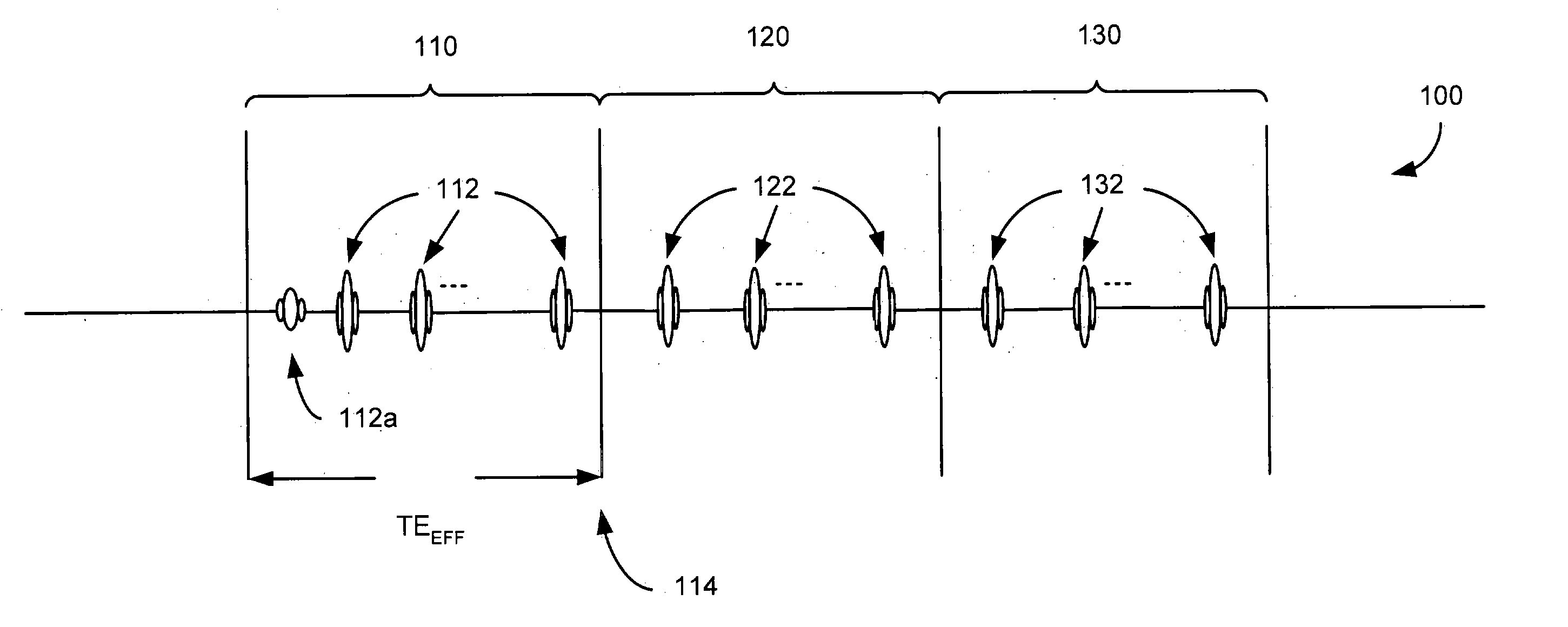
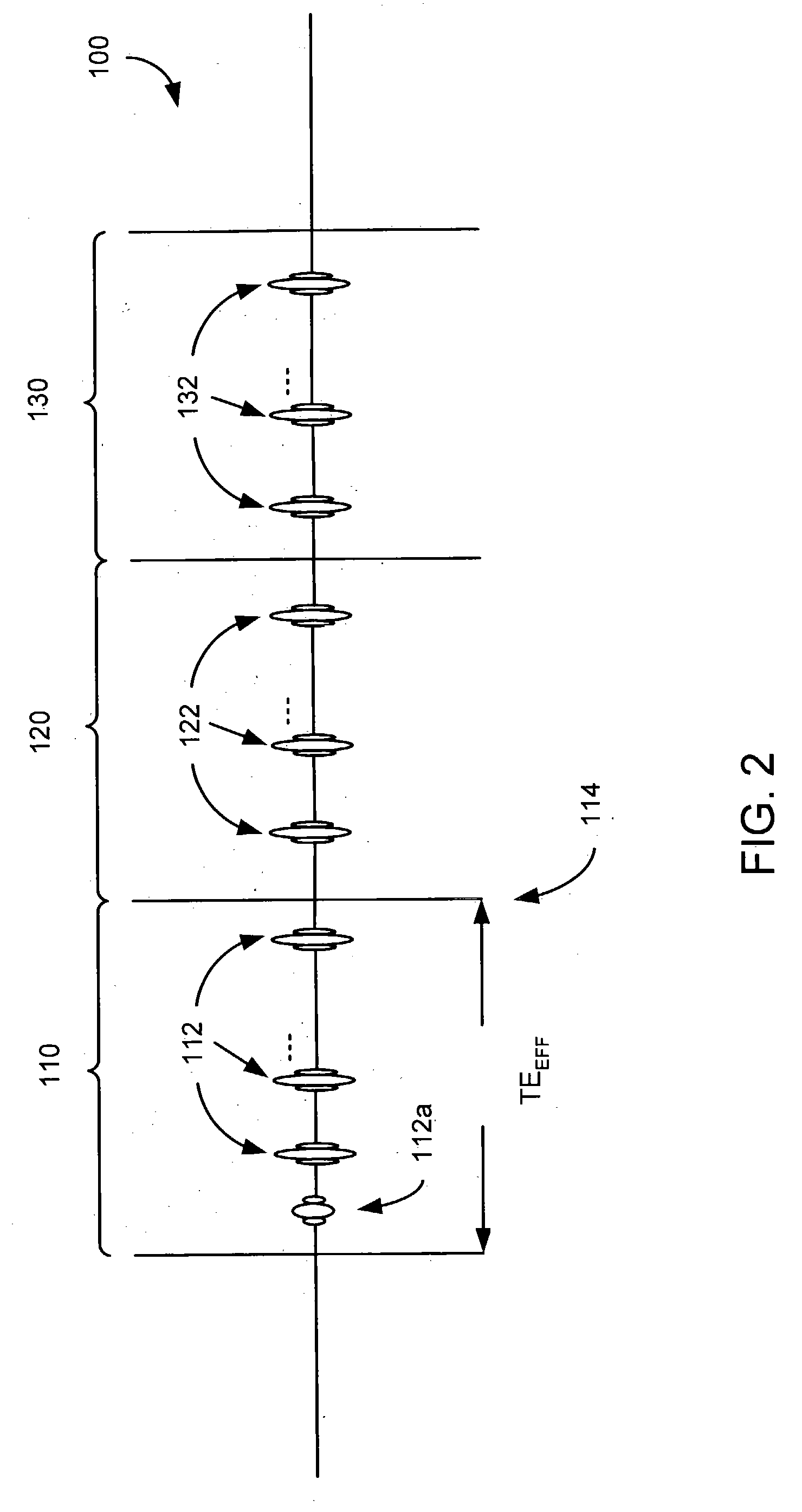
The technique of the present invention reduces RF power deposition at high field strengths by implementing two complementary approaches. First, individual RF pulses and slice-select gradients are reshaped using the variable rate selective excitation (VERSE) technique, and then the flip angles of the refocusing pulse train are varied from pulse to pulse using a modulated angle refocusing train. The modulated angle refocusing train employs high flip angle pulses prior to sampling the center of k-space in order to preserve T2 contrast. Low flip angles are then utilized after sampling the center of k-space to reduce power and prolong relaxation. A smooth transition is provided between the high and low flip angle phases in order to maintain the pseudo-steady-state, thereby maximizing signal and avoiding artifact-inducing oscillations. Such a pulse sequence can reduce induced RF power by 75% without affecting contrast and with only a small decrease in SNR, while providing improved resolution over prior art techniques.
The invention also includes a method for reducing RF power induced in a patient during high field MR imaging. The process includes applying a set of RF pulses with relatively high flip angles to preserve T2 contrast before a first TE, and then after the first TE, applying a set of RF pulses with varying flip angles that are lower than that applied before the first TE.

Problems solved by technology

High field imaging can theoretically provide a significant improvement in signal-to-noise ratio (SNR) compared to imaging at lower field strengths, but it is also burdened by a quadratic increase in peak and integrated RF power as a function of field strength.
That is, peak power capacity of the system limits how compact a given RF pulse can be made.
Further, limitations on average power induced in the patient further limits how quickly pulses can be repeated and thus, how much coverage can be attained in a given amount of time.
Certain pulse sequences, such as fast spin echo sequences, are designed to operate at or near regulatory power limits at low field strengths and therefore require particular challenges for use in high field strength to limit the amount of induced RF power.
Particularly, standard 180° pulses that are used for refocusing must be limited significantly, and the advantages of high field imaging can thereby be lost.
However, increasing the echo spacing also causes increased modulation due to relaxation.
In other words, stretching RF pulses can result in longer echo spacing, but then exacerbate the effects of relaxation through the echo train, thereby resulting in degraded image quality.
However, this technique still suffers reduced image quality because it is sensitive to off-resonance and therefore produces weakened signals that reduce SNR in the presence of off-resonance.
By increasing the flip angle for acquisition of low k-space views, SNR can be improved, however this also has the detrimental effect of increasing blurring.

Method used


Image

  • Method and apparatus to reduce RF power in high field MR imaging incorporating multi-phase RF pulse flip angles
  • Method and apparatus to reduce RF power in high field MR imaging incorporating multi-phase RF pulse flip angles
  • Method and apparatus to reduce RF power in high field MR imaging incorporating multi-phase RF pulse flip angles

Examples


Embodiment Construction

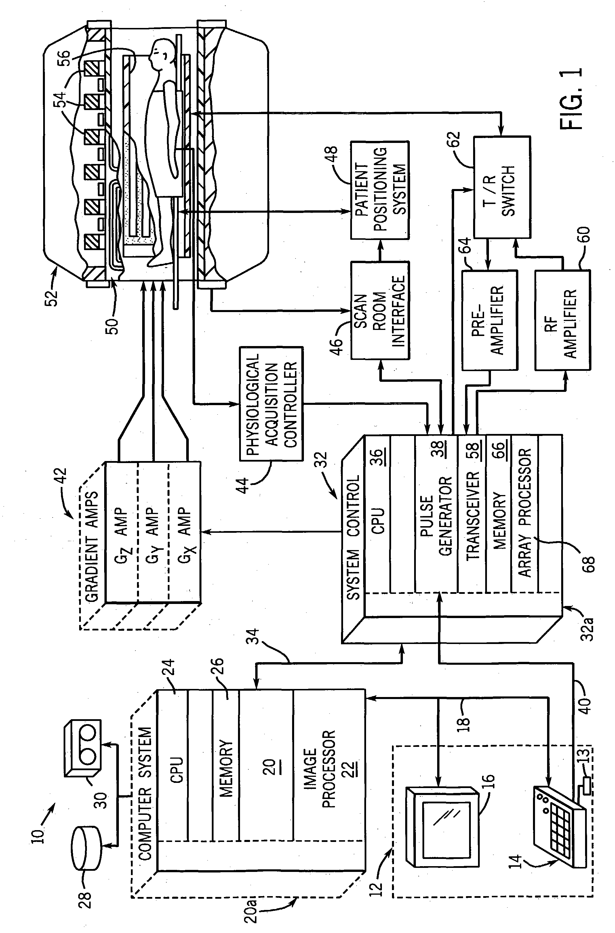
Referring to FIG. 1, the major components of a preferred magnetic resonance imaging (MRI) system 10 incorporating the present invention are shown. The operation of the system is controlled from an operator console 12 which includes a keyboard or other input device 13, a control panel 14, and a display screen 16. The console 12 communicates through a link 18 with a separate computer system 20 that enables an operator to control the production and display of images on the display screen 16. The computer system 20 includes a number of modules which communicate with each other through a backplane 20a. These include an image processor module 22, a CPU module 24 and a memory module 26, known in the art as a frame buffer for storing image data arrays. The computer system 20 is linked to disk storage 28 and tape drive 30 for storage of image data and programs, and communicates with a separate system control 32 through a high speed serial link 34. The input device 13 can include a mouse, jo...


PUM


Abstract

A technique is set forth that is designed to reduce RF induced power in high field MR imaging that includes application of an initial contrast preserving phase of RF pulses. These initial RF pulses are designed to have a constant, relatively high flip angle over the initial contrast preserving phase. Following an effective TE, a ramp down phase is applied that has a limited number of RF pulses with a flip angle that is less than the flip angle of those in the initial contrast preserving phase. Further, the RF pulses in the ramp down phase have a flip angle that is decreased over the ramp down phase. This technique provides improved resolution and steady contrast and SNR, while significantly reducing induced RF power.

Description

BACKGROUND OF THE INVENTION The present invention relates generally to a magnetic resonance imaging (MRI), and more particularly, to a method and apparatus for reduction of RF induced power in high field imaging using a modulated pulse sequence. When a substance such as human tissue is subjected to a uniform magnetic field (polarizing field Bo), the individual magnetic moments of the spins in the tissue attempt to align with this polarizing field, but precess about it in random order at their characteristic Larmor frequency. If the substance, or tissue, is subjected to a magnetic field (excitation field B1) which is in the x-y plane and which is near the Larmor frequency, the net aligned, moment, or “longitudinal magnetization”, MZ, may be rotated, or “tipped”, into the x-y plane to produce a net transverse magnetic moment Mt. A signal is emitted by the excited spins after the excitation signal B1 is terminated and this signal may be received and processed to form an image. When ...

Claims


Application Information

Patent Timeline
IPC IPC(8): A61B5/055G01R33/48G01R33/561
CPCG01R33/5613
Inventor BUSSE, REED F.
Owner GENERAL ELECTRIC CO
Learn More