Matching layer assembly for a downhole acoustic sensor

a technology of matching layer and acoustic sensor, which is applied in the field of downhole measurement tools, can solve the problems of acoustic sensor subject to various (often severe) mechanical forces, limited use, and limited reliability of acoustic sensor, so as to improve the signal-to-noise ratio of downhole acoustic measurement, improve reliability, and improve the robustness to the downhole environment

Active Publication Date: 2005-01-06
SCHLUMBERGER TECH CORP
View PDF99 Cites 35 Cited by
  • Summary
  • Abstract
  • Description
  • Claims
  • Application Information

AI Technical Summary

Benefits of technology

[0008] Exemplary embodiments of the present invention advantageously provide several technical advantages. Various embodiments of the acoustic sensor of this invention may withstand the extreme temperatures, pressures, and mechanical shocks frequent in downhole environments. Tools embodying this invention may thus display improved reliability as a result of the improved robustness to the downhole environment. Exemplary embodiments of this invention may further advantageously improve the signal to noise ratio of downhole acoustic measurements and thereby improve the sensitivity and utility of such measurements.

Problems solved by technology

While prior art acoustic sensors have been used in various downhole applications (as described in the previously cited U.S. patents), their use, particularly in logging while drilling (LWD) and measurement while drilling (MWD) applications, tends to be limited by various factors.
Most prior art acoustic measurement systems encounter serious problems that result directly from the exceptional demands of the drilling environment.
Further, the acoustic sensors are subject to various (often severe) mechanical forces, including shocks and vibrations up to 650 G per millisecond.
Mechanical abrasion from cuttings in the drilling fluid, and direct hits on the sensor face (e.g., from drill string collisions with the borehole wall) have been known to damage or even fracture the piezoelectric element.
Existing acoustic measurement systems also tend to be limited in downhole environments by transducer ringing and a relatively poor signal to noise ratio (as compared to, for example, transducers used in other applications).
As such, typical prior art acoustic sensors are typically imprecise at measuring distances outside of a relatively narrow measurement range.
At relatively small distances (e.g., less than about one centimetre) acoustic measurements tend to be limited by residual transducer ringing and other near field limitations related to the geometry of the transducer.

Method used


Image

  • Matching layer assembly for a downhole acoustic sensor
  • Matching layer assembly for a downhole acoustic sensor
  • Matching layer assembly for a downhole acoustic sensor

Examples


Embodiment Construction

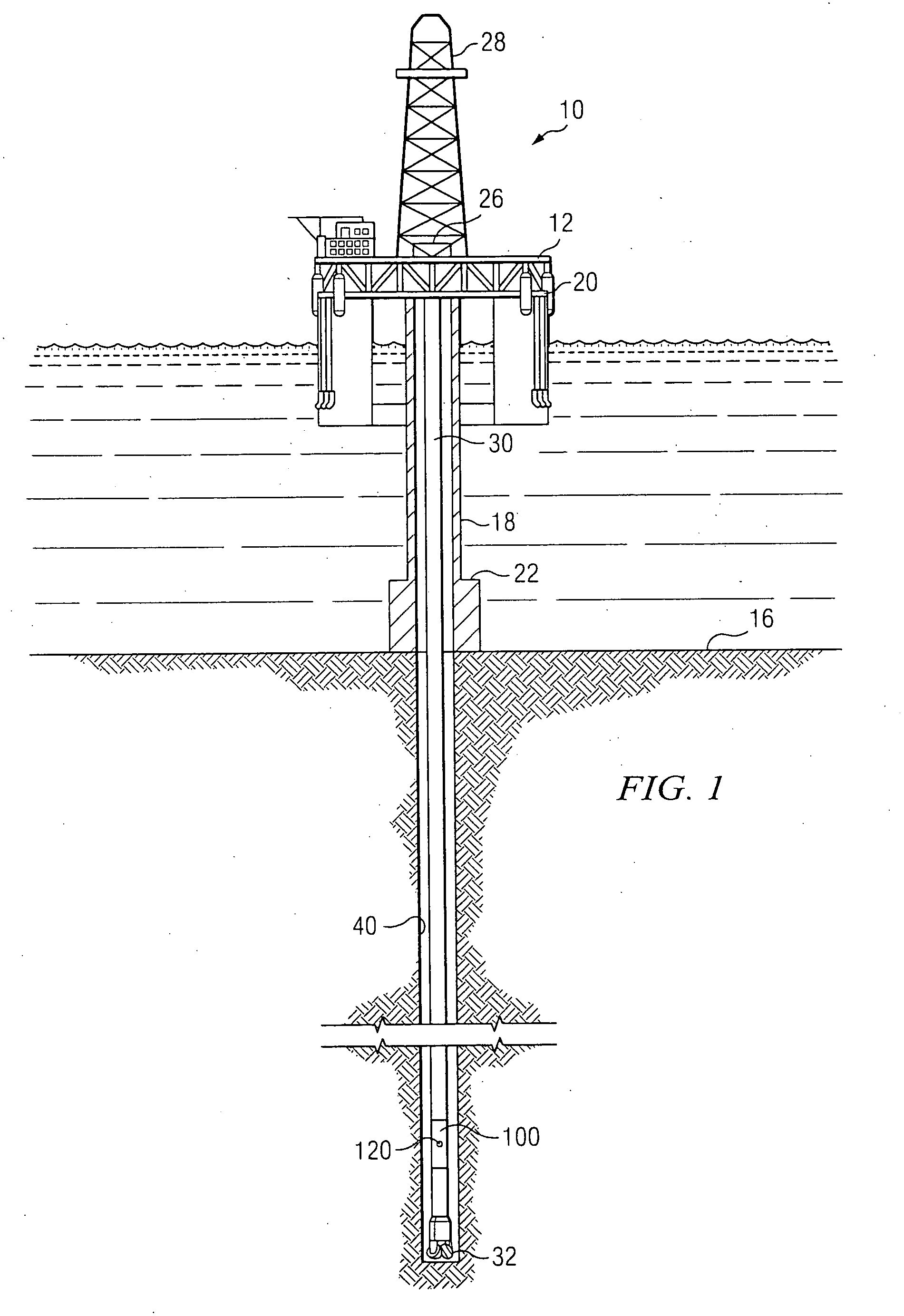
[0025]FIG. 1 schematically illustrates one exemplary embodiment of a measurement tool 100 according to this invention in use in an offshore oil or gas drilling assembly, generally denoted 10. In FIG. 1, a semisubmersible drilling platform 12 is positioned over an oil or gas formation (not shown) disposed below the sea floor 16. A subsea conduit 18 extends from deck 20 of platform 12 to a wellhead installation 22. The platform may include a derrick 26 and a hoisting apparatus 28 for raising and lowering the drill string 30, which, as shown, extends into borehole 40 and includes a drill bit 32 and an acoustic measurement tool 100 including at least one acoustic sensor 120. Drill string 30 may further include a downhole drill motor, a mud pulse telemetry system, and one or more other sensors, such as a nuclear logging instrument, for sensing downhole characteristics of the borehole and the surrounding formation.

[0026] It will be understood by those of ordinary skill in the art that th...


PUM


Abstract

An acoustic sensor for use in a downhole measurement tool is provided. The acoustic sensor includes a piezoelectric transducer and a matching layer assembly having at least one matching layer and a barrier layer. In various exemplary embodiments, the at least one matching layer includes first and second matching layers formed from a glass ceramic work piece and the barrier layer includes corrugated titanium. Exemplary embodiments of this invention may advantageously withstand the extreme temperatures, pressures, and mechanical shocks frequent in downhole environments and thus may exhibit improved reliability. A method for fabricating an acoustic sensor is also provided.

Description

FIELD OF THE INVENTION [0001] The present invention relates generally to downhole measurement tools utilized for measuring properties of a subterranean borehole during drilling operations. More particularly, this invention relates to a matching layer assembly for an acoustic sensor used in a downhole measurement tool. Embodiments of the matching layer assembly include at least one matching layer and a barrier layer formed from a metallic material. BACKGROUND OF THE INVENTION [0002] The use of acoustic (e.g., ultrasonic) measurement systems in prior art downhole applications, such as logging while drilling (LWD), measurement while drilling (MWD), and wireline logging applications is well known. In known systems an acoustic sensor operates in a pulse-echo mode in which it is utilized to both send and receive a pressure pulse in the drilling fluid (also referred to herein as drilling mud). In use, an electrical drive voltage (e.g., a square wave pulse) is applied to the transducer, whi...

Claims


Application Information

Patent Timeline
Patent Type & Authority Applications(United States)
IPC IPC(8): G01V1/18G01V1/52H04R1/20
CPCG01V1/52G01V1/186
Inventor YOGESWAREN, ELAN
Owner SCHLUMBERGER TECH CORP
Why Eureka
Try Eureka