Flash evaporation-plasma coating deposition method

a technology of plasma and evaporation, applied in the field of coatings, can solve the problems of lack of carbon powder formation, and inability to achieve the effect of evaporation,

Inactive Publication Date: 2005-01-06
3M INNOVATIVE PROPERTIES CO
View PDF98 Cites 54 Cited by
  • Summary
  • Abstract
  • Description
  • Claims
  • Application Information

AI Technical Summary

Benefits of technology

The present invention provides a method for the formation of an organic coating on a substrate comprising: providing a substrate in a vacuum; providing at least one vaporized organic material comprising at least one component from at least one source, wherein the vaporized organic material is capable of condensing in a vacuum of less tha

Problems solved by technology

Methods for preparing coatings by plasma deposition, i.e., plasma-enhanced chemical vapor deposition, are known; however, some of these methods have deficiencies.
For example, with certain methods the use of high gas flow, pressure, and power can cause formation

Method used


Image

  • Flash evaporation-plasma coating deposition method
  • Flash evaporation-plasma coating deposition method
  • Flash evaporation-plasma coating deposition method

Examples


example 1

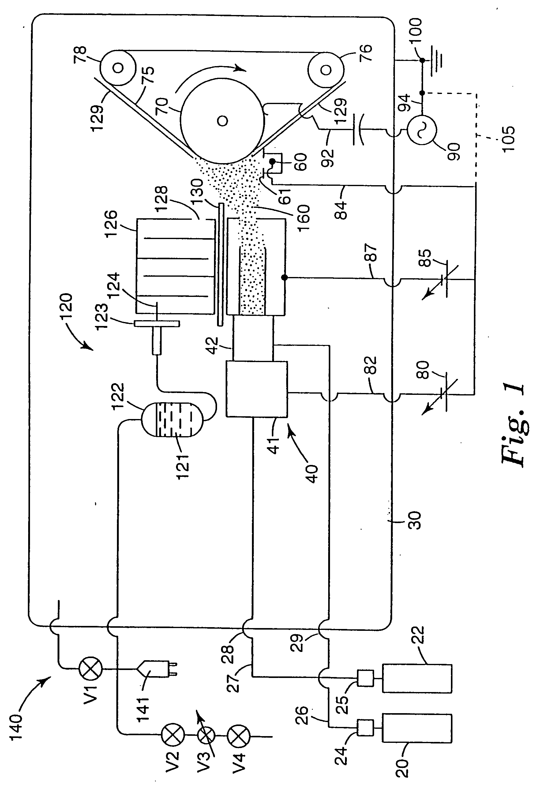
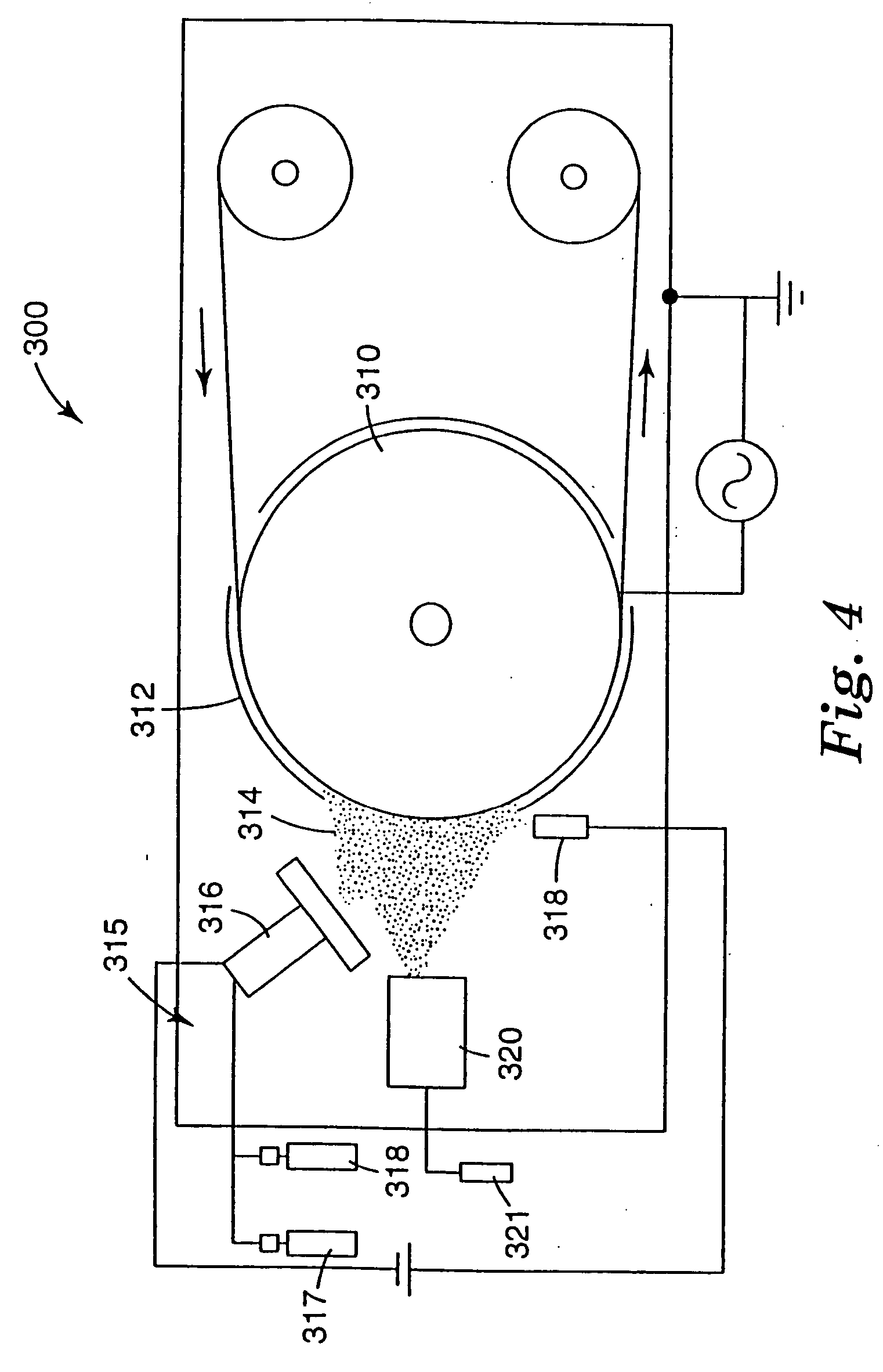
Silicone coatings were deposited on 30 cm wide and 0.074 mm thick untreated polyethylene terephthalate (PET) in the system shown in FIG. 4. The system is similar to the deposition chamber described in U.S. Pat. No. 5,464,667 (Kohler et al.) with several modifications, including a point source cathode and an oil delivery system.

The system included a biased chill roll, 48.2 cm in diameter and 33.5 cm wide. Except for the deposition area, about 76% of the surface of the radio frequency bias electrode was covered by an aluminum sheet. The aluminum sheet was grounded and placed about 0.6 cm away from the surface to provide a dark space and thus concentrated the bias wattage over the remaining 24% of the surface area. An imaginary horizontal plane could be drawn from the center of the radio frequency bias electrode to the slot opening of the oil delivery system, dividing the noncovered surface area in half. The point source cathode was placed about 7.5 cm above the imaginary plane and ...

example 2

Carbon-rich coatings were deposited on 30 cm wide and 1.4×10⁻³ cm thick video grade polyethylene terephthalate (PET) film having therein less than about 1% SiO2 slip agent (OX-50 from Degussa of Germany), which had been corona treated and wrapped for storage and handling in a packaging film with moisture barrier characteristics (manufactured by 3M Company, St. Paul, Minn.). The experiment was similar to Example 3 of U.S. Pat. No. 5,464,667 (Kohler et al.), which is incorporated herein by reference, except that the hollow cathode slot was replaced by the hollow cathode point source (i.e., point source cathode) described above in Example 1. The development of the point source cathode simplified the cathode system and eliminated several components of the hollow cathode slot system, including the argon plasma compartment together with the argon plasma power supply and the acetylene compartment.

The point source cathode was placed about 17.5 cm away from the biased chill roll. After th...

example 3

Silicone coatings were deposited on 15 cm wide and 2.54×10⁻³ cm thick film available under the trade designation “KAPTON” film from DuPont de Nemours (Wilmington, Del.), Type 100H. Except for the addition of an oil delivery system (described above) all other components of the deposition system were identical to those described in Example I of U.S. Pat. No. 5,464,667 (Kohler et al.); however, the arrangement of the deposition system was modified. The hollow cathode slot system was 9 cm away from the chill roll. Drawing an imaginary horizontal plane from the center of the radio frequency bias electrode to the cathode, the cathode slot was about 1.6 cm below the plane. The anode wire was about 4 cm away from the cathode slot and about 6 cm below the imaginary plane. A Pyrex glass plate (20 cm wide, 5 cm long, 0.3 cm thick) was placed parallel to and about 0.6 cm below the imaginary plane reaching from the front of the cathode box toward the radio frequency bias electrode and leaving a...


PUM

PropertyMeasurementUnit
Fractionaaaaaaaaaa
Fractionaaaaaaaaaa
Pressureaaaaaaaaaa

Abstract

The present invention provides a method for the formation of an organic coating on a substrate. The method includes: providing a substrate in a vacuum; providing at least one vaporized organic material comprising at least one component from at least one source, wherein the vaporized organic material is capable of condensing in a vacuum of less than about 130 Pa; providing a plasma from at least one source other than the source of the vaporized organic material; directing the vaporized organic material and the plasma toward the substrate; and causing the vaporized organic material to condense and polymerize on the substrate in the presence of the plasma to form an organic coating.

Description

FIELD OF THE INVENTION The present invention relates to coatings, particularly organic coatings containing carbon and / or silicon coatings, and to a method and apparatus for the plasma deposition of such coatings. BACKGROUND OF THE INVENTION Plasma processes offer the opportunity to make coatings that can be quite hard, chemically inert, corrosion resistant, and impervious to water vapor and oxygen. These are often used as mechanical and chemical protective coatings on a wide variety of substrates. For example, carbon-rich coatings (e.g., diamond-like carbon and jet plasma carbon coatings) have been applied to rigid disks and flexible magnetic media. They have also been applied to acoustic diaphragms, polymeric substrates used in optical and ophthalmic lenses, as well as electrostatic photographic drums. Silicon-containing polymer coatings have been applied to polymeric and metal substrates for abrasion resistance. Also, silicone coatings have been applied to polymeric and nonpolym...

Claims


Application Information

Patent Timeline
IPC IPC(8): B05D7/24C23C16/448C23C16/50C23C16/513H01J37/32
CPCB05D1/62C23C16/4485Y10T428/273Y10T428/269C23C16/513Y10T428/31663C23C16/26C23C16/401
Inventor KOHLER, QUNTER A.ESSWEIN, WILLIAM H.KIRK, SETH M.GATES, BRIAN J.
Owner 3M INNOVATIVE PROPERTIES CO
Why Eureka
Try Eureka