Attitude measurement using a single GPS receiver with two closely-spaced antennas

a technology of gps receiver and antenna, applied in direction finders, navigation instruments, instruments, etc., can solve the problems of requiring costly hardware components, limiting the maneuvering on the platform, and not taking full advantage of the available gps and imu measurements, so as to improve accuracy and reduce cost. , the effect of cost advantages

Inactive Publication Date: 2005-01-06
ENPOINT
View PDF20 Cites 73 Cited by
  • Summary
  • Abstract
  • Description
  • Claims
  • Application Information

AI Technical Summary

Benefits of technology

The principles of the present invention include at least five innovations: Utilization of available spare capacity within commercially available low cost GPS receivers enables GPS interferometry using only a single GPS receiver. This provides both cost advantages and accuracy improvement because the same oscillator is used for downconversion of both GPS antenna signals. Close spacing of two GPS antennas, down to about 3 inches, depending on accuracy requirements of the application. This enables simplified packaging, with less space involvement, and installation to the mobile platforms. Close antenna spacing also minimizes the effects of multipath interference on the attitude solution. Tight integration of the single-GPS-antenna transfer alignment process with the dual-antenna GPS interferometry process. This yields heading estimation independent of the GPS interferometry solution so that heading ambiguities normally resulting from interferometric solu

Problems solved by technology

The prior art provides approaches to the commercial requirements; however, each of the prior art approaches must be tailored to the specific platforms, requires costly har

Method used


Image

  • Attitude measurement using a single GPS receiver with two closely-spaced antennas
  • Attitude measurement using a single GPS receiver with two closely-spaced antennas
  • Attitude measurement using a single GPS receiver with two closely-spaced antennas

Examples


Embodiment Construction

A description of preferred embodiments of the invention follows.

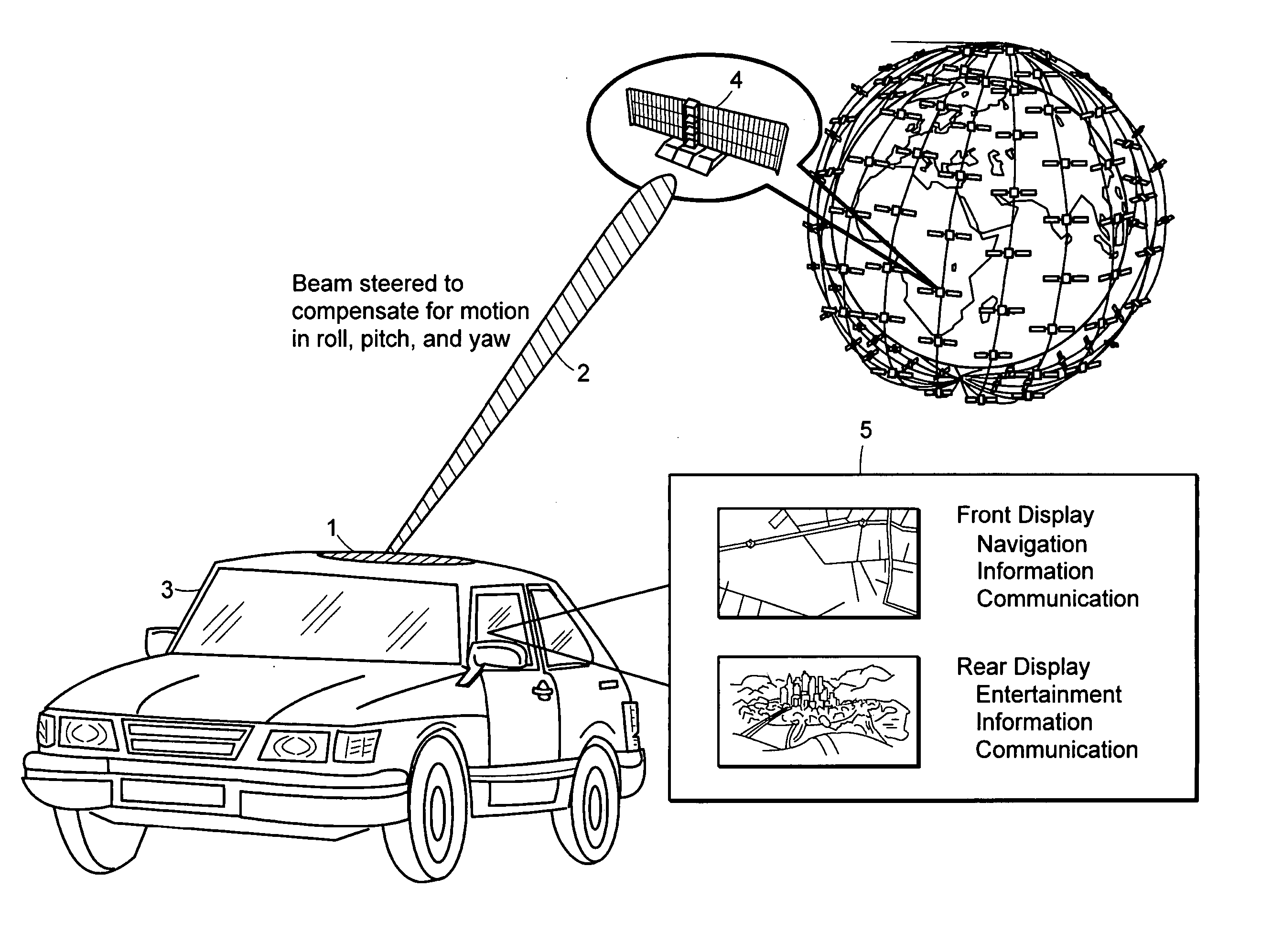
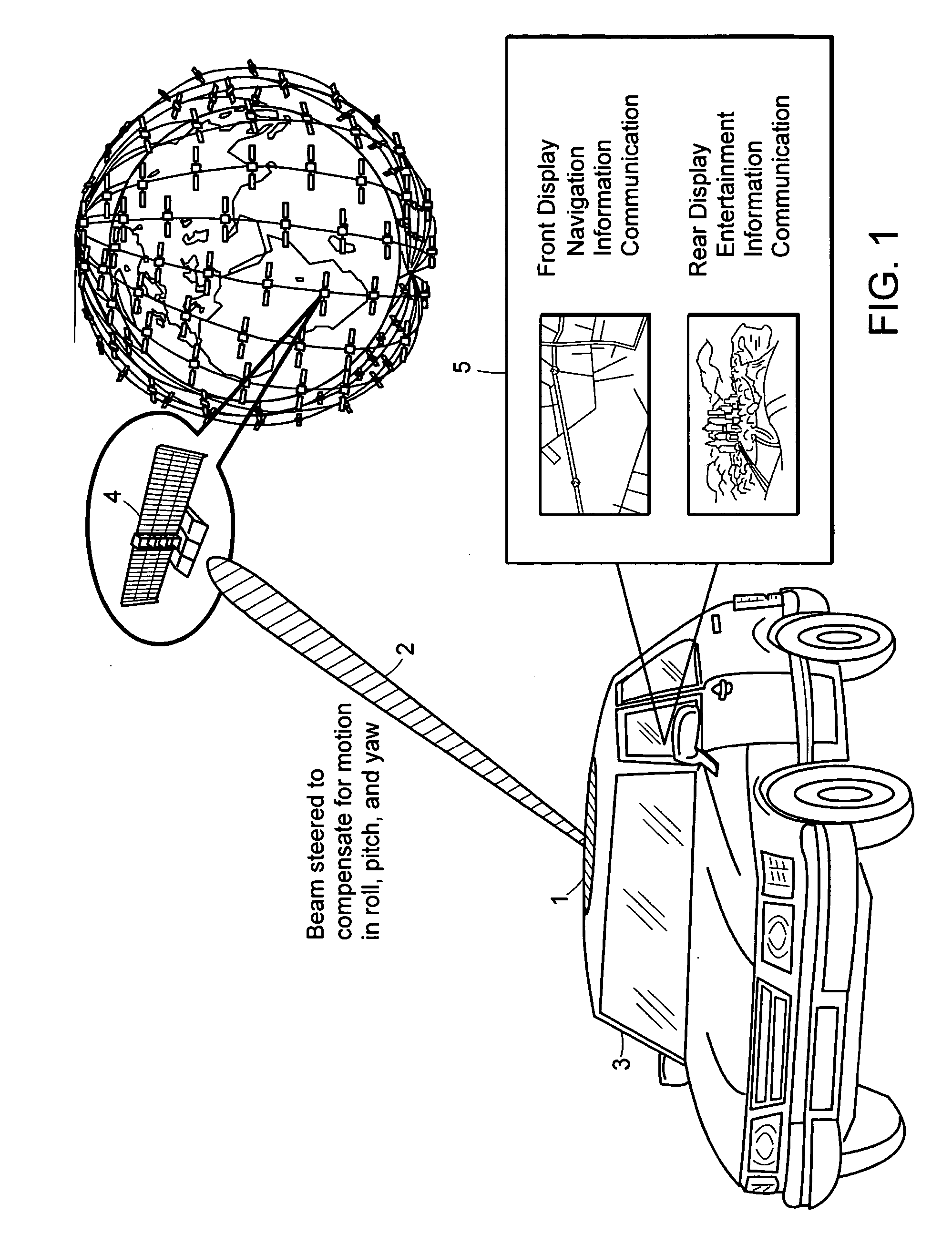
The current explosive growth in mobile vehicle display products is accompanied by increased demand for robust access to high-quality spatial information and to broadband data sources, such as streaming video, digital television, and high definition television (HDTV). The present invention can be used to facilitate delivery of multimedia broadband data to users in vehicles, such as cars, planes, trains, boats, and airplanes. New generations of satellite-based broadband delivery systems use Low Earth Orbit (LEO) satellites operating at 20 GHz or higher frequencies and require precise pointing of highly directional antennas to achieve high data rates.

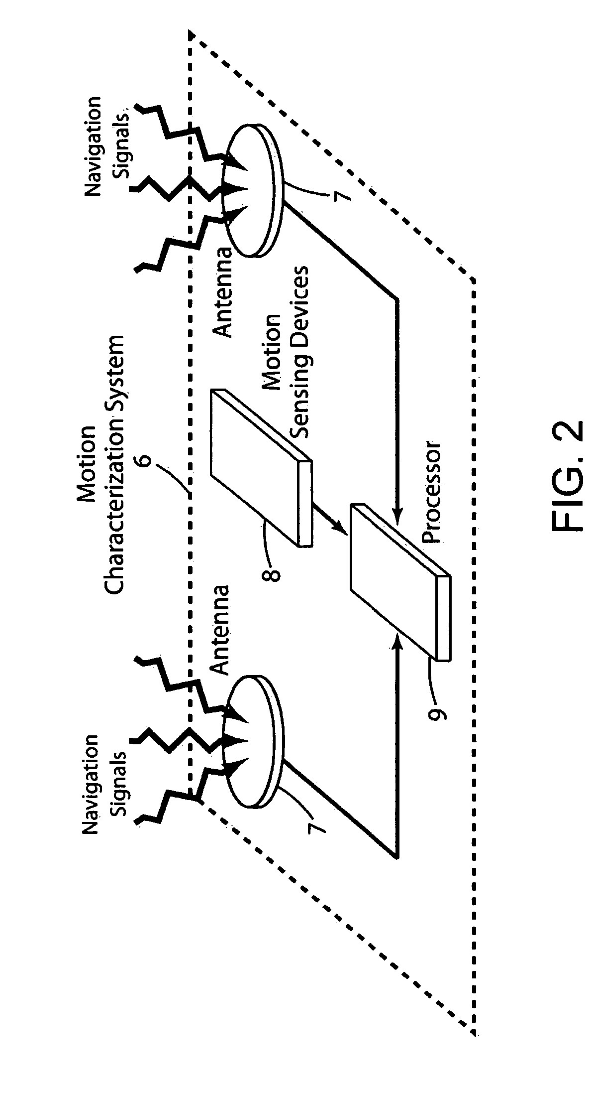
The present invention permits use of poor performance, low-cost motion sensing devices both to enable accurate, affordable, antenna pointing solutions for broadband mobile communications and to permit the robust delivery of spatial information to both military and commercia...


PUM


Abstract

A system determines three-dimensional attitude of a moving platform using signals from two closely spaced Global Positioning System (GPS) antennas. The system includes three rate gyroscopes and three accelerometers rigidly mounted in a fixed relationship to the platform to aid in determining the attitude. The system applies signals from one of the two GPS antennas to sufficient channels of a GPS receiver to support navigation. The system applies signals from a second of the two GPS antennas to the additional receive channels to support interferometry. The system resolves the ambiguity normally associated with the interferometric heading solution by having closely spaced GPS antennas, and uses interferometry to refine a coarse heading estimate from a GPS plus Inertial Measurement Unit (IMU) transfer alignment solution. The system achieves sub-meter spacing of the two GPS antennas by merging many temporal interferometric measurements and the attitude memory provided by the IMU time-history solution.

Description

BACKGROUND OF THE INVENTION The present invention relates to moving platforms, specifically, to a system for determining the geodetic attitude of an arbitrarily moving platform. Moving platforms include vehicles, such as aircraft, ground vehicles, boats or spacecraft or equipment mounted to vehicles that can be reoriented relative to the vehicle body. The platforms may be traveling at fast or slow speeds, may be maneuvering or non-maneuvering, and may be occasionally stationary relative to geodetic space. These platforms require knowledge of their geodetic attitude in order, for example, (i) to support safety or stability control systems, (ii) to point an antenna or sensor boresight at a geodetically known target, (iii) to control their geodetic position or attitude movement, or (iv) to register the information sensed along the boresight onto a map projection with geodetic coordinates. The sensor or antenna boresight is the centerline of some signal collection or signal transmissio...

Claims


Application Information

Patent Timeline
IPC IPC(8): G01S19/48G01C21/16G01S3/48G01S5/14G01S19/11G01S19/21G01S19/26G01S19/36G01S19/53G01S19/54
CPCG01C21/165G01S3/48G01S19/54G01S19/53G01S19/36G01S19/26
Inventor PINTO, ROBERTKAIN, JAMES
Owner ENPOINT
Why Eureka
Try Eureka