Capacitive sensor

a capacitance sensor and capacitance technology, applied in the field of capacitance sensors, can solve the problems of reducing the electric charge of the capacitance cf, the output voltage of the amplifier is unstable, and the noise of the wires is significant, so as to reduce the noise between the sensing unit and the filter effect of low frequency

Inactive Publication Date: 2005-01-13
ALPS ALPINE CO LTD
View PDF5 Cites 85 Cited by
  • Summary
  • Abstract
  • Description
  • Claims
  • Application Information

AI Technical Summary

Benefits of technology

[0020] In this configuration, low-frequency noise occurri

Problems solved by technology

Unfortunately, in the above-described detecting circuit of the pressure-sensitive capacitive sensor, when a small sensor capacitance Cs is measured, since an output voltage of the switched capacitor circuit is inversely proportional to the feedback capacitance Cf, the capacitance Cf must be small to obtain a large output voltage.
Accordingly, a significant amount of noise from the wires, the human body, and a power supply appears.
Additionally, even if the circuit is completely shielded, a required electrical current for mai

Method used


Image

  • Capacitive sensor
  • Capacitive sensor
  • Capacitive sensor

Examples


first embodiment

[0034] the present invention will now be described with reference to the accompanying drawings.

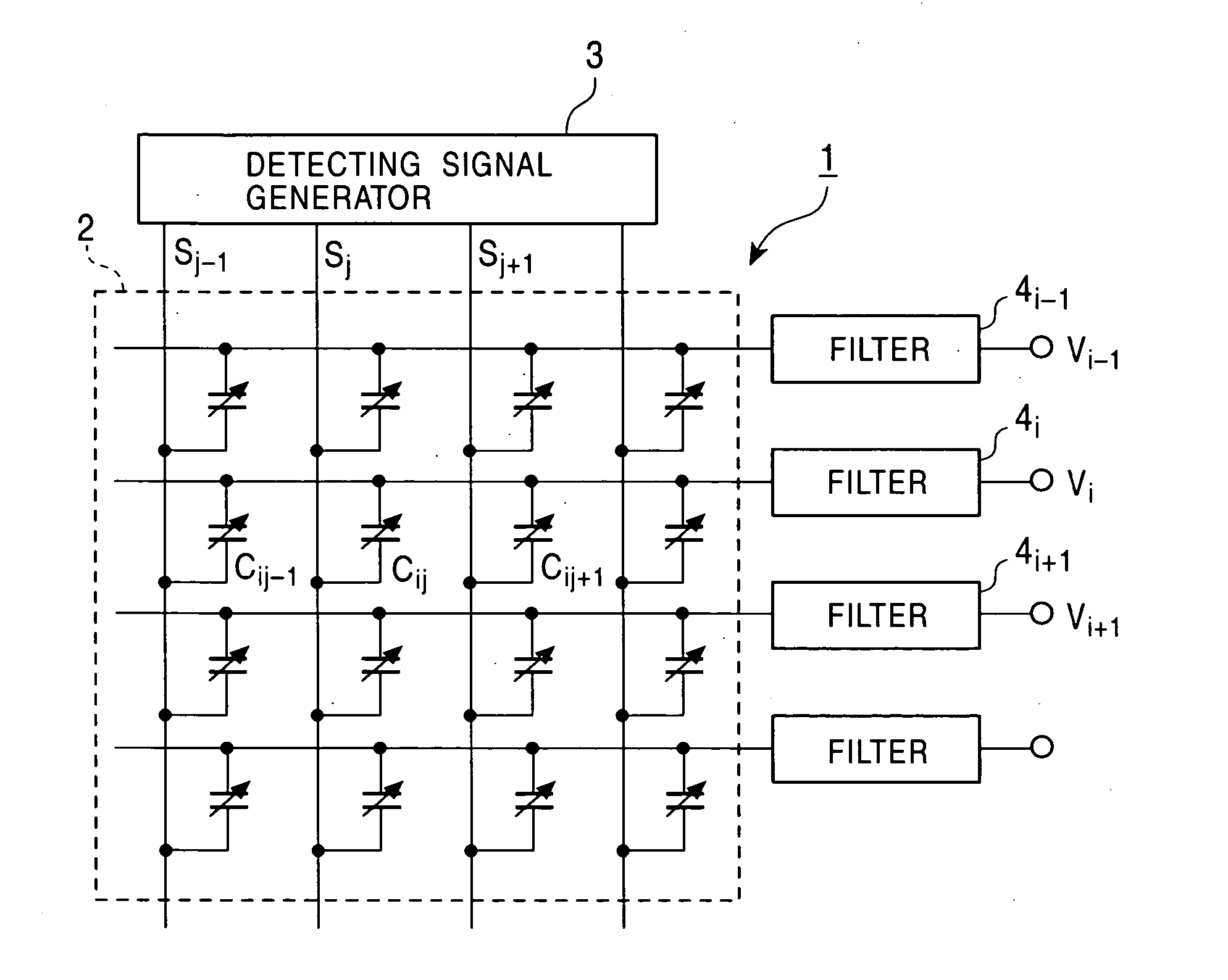
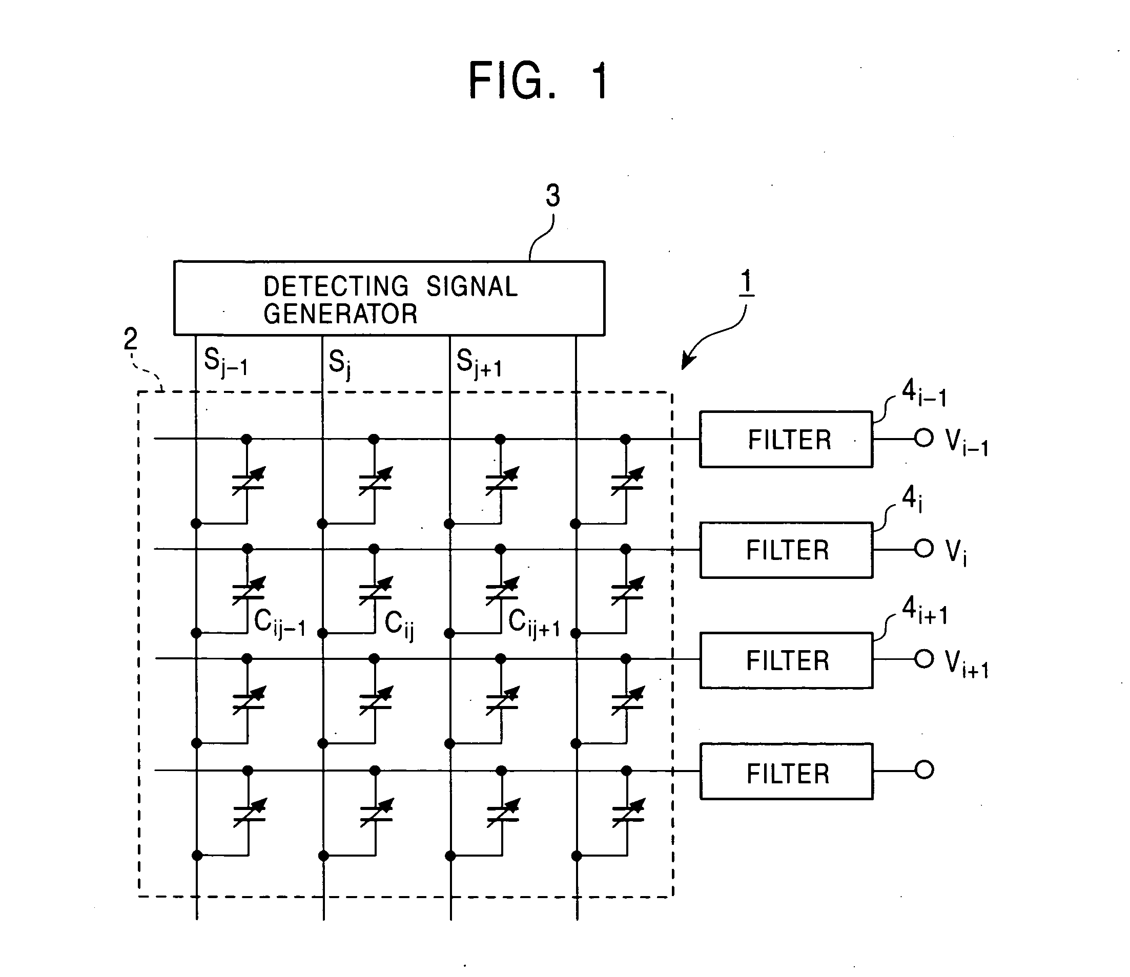
[0035]FIG. 1 is a block diagram of a capacitive sensor 1 according to the embodiment. The capacitive sensor 1 includes a sensing unit 2 with which a target object, for example, a fingertip is brought into contact; a detecting signal generator 3 which outputs detecting signals to the sensing unit 2; filters 4i−1, 4i, 4i+1, . . . which receive output signals from the sensing unit 2; and a processing circuit (not shown) which processes outputs from the filters 4i−1, 4i, 4i+1.

[0036] The sensing unit 2 has first and second opposing flexible thin plates with a small spacing therebetween. A plurality of column wires are evenly formed on the first thin plate, while a plurality of row wires are evenly formed on the second thin plate in the direction perpendicular to the column wires. Urging a fingertip onto the sensing unit 2 changes the spacings between the column wires and the row wires at their...

second embodiment

[0050] the present invention will now be described.

[0051]FIGS. 5 and 6 are block diagrams of a capacitive sensor according to the second embodiment. Elements identical to those illustrated and described in relation to FIG. 1 are designated by like reference numerals. In FIG. 5, a sensing unit 2 and a detecting signal generator 3 have the same configurations as those having like reference numerals in FIG. 1. A filter 4 has the same configuration as each of the filters 4i−1, 4i, 4i+1, . . . shown in FIG. 1. A selector 11 selects one of the row wires based on a select signal SEL and connects the wire to an input terminal of the filter 4.

[0052]FIG. 6 is a configuration of a capacitive sensor having a control circuit 12 in addition to the above-described configuration. In the control circuit 12, an amplifier 13 amplifies an output signal from the filter 4 and outputs it. An amplitude detector 14 sequentially outputs analog signals corresponding to amplitudes of signal waves sequentially...

third embodiment

[0062] the present invention will now be described. FIG. 11 is a top view of electrodes. Second comb-shaped electrodes 22 extend from a column wire 21, while first comb-shaped electrodes 25 extend from a row wire 24. FIG. 12 is a cross-sectional view of the electrodes. The second electrodes 22 are formed on a different plane from the first electrodes 25. The first electrodes 25 are formed on a glass substrate 26 and are covered with a first insulating film 28. The second electrodes 22 are formed on the first insulating film 28 and are covered with a second insulating film 29. If these wires and electrodes are made of, for example, indium tin oxide (ITO), which is transparent, and the first insulating film 28 and the second insulating film 29 are made of silicon nitride (SiNx), the detecting device can be light-transmitting.

[0063]FIGS. 13A and 13B illustrate a mechanism by which the electric capacitance between the second electrodes 22 and the first electrodes 25 changes. FIG. 13A sh...


PUM


Abstract

A pressure-sensitive capacitive sensor includes a sensing unit in which a plurality of column wires and a plurality of row wires are formed in a matrix, a detecting signal generator, and filters. Capacitances at intersections between the column wires and the row wires change in accordance with externally applied pressure. The detecting signal generator sequentially outputs pulse signals of a predetermined frequency to the column wires of the sensing unit. The filters are connected to the respective row wires of the sensing unit and extract amplitudes of signals of the predetermined frequency. The amplitude is proportional to the capacitance at the intersection.

Description

BACKGROUND OF THE INVENTION [0001] 1. Field of the Invention [0002] The present invention relates to a capacitive sensor mainly used as a fingerprint sensor. [0003] 2. Description of the Related Art [0004] A pressure-sensitive capacitive sensor has been known as a fingerprint sensor, which is most promising in biometric security applications, such as a biometric identification. Such a pressure-sensitive capacitive sensor has two films respectively having column wires and row wires at predetermined pitches on their surfaces, and an insulating layer between the films having a predetermined distance. In the pressure-sensitive capacitive sensor, when a finger touches the film, the film is deformed in accordance with the shape of the fingerprint and the spacing between the column wires and row wires varies depending on the position on the film. Thus, the shape of the fingerprint is detected from capacitances at intersections of the column wires and row wires. In a known technology, to de...

Claims


Application Information

Patent Timeline
IPC IPC(8): A61B5/117G01B7/28G01L5/00G01D5/24G01L9/12G01R27/26G06F3/041G06F3/044G06K9/00G06T1/00
CPCA61B5/1172G01L9/12G06K9/0002G06F3/0414G06F3/044G01R27/2605G06F3/0446G06V40/1306G01R23/165
Inventor SAITO, JUNICHIUMEDA, YUICHI
Owner ALPS ALPINE CO LTD
Why Eureka
Try Eureka