Supercharge Your Innovation With Domain-Expert AI Agents!

Method for preventing formation of photoresist scum

a photoresist and scum technology, applied in the field of semiconductor process, can solve the problems of difficult removal, device failure, and serious affecting the electrical properties of the device, and achieve the effect of preventing the formation of photoresist scum and preventing nitrogen from contaminating the photoresis

Inactive Publication Date: 2005-01-13
TSMC CHINA COMPANY
View PDF10 Cites 6 Cited by
  • Summary
  • Abstract
  • Description
  • Claims
  • Application Information

AI Technical Summary

Benefits of technology

"The present invention provides a method for preventing the formation of photoresist scum during a semiconductor device manufacturing process. This is achieved by using a non-nitrogen material as the anti-reflective layer to prevent nitrogen from contaminating the photoresist. Additionally, a barrier layer can be added to prevent nitrogen from diffusing into the dielectric layer. This method can be used in a dual damascene process to form a structure with reduced photoresist scum."

Problems solved by technology

Thus, during the development procedure, amine (NHx) photoresist scum remains, in turn forming an inaccurate pattern and seriously affecting the electrical properties of the device.
Photoresist scum 110b, detrimental to subsequent metallization and causing device failure, and is very difficult to remove even by photoresist stripping.
However, after plasma descumming, the photoresist pattern layer thins and has decreased etching resistance.
Also, the resulting pattern will be larger than the original design, which in turn changes the electrical properties of the device and does not meet the original device requirements.
Although the photoresist scum problem is solved, the production cost increases.

Method used


Image

  • Method for preventing formation of photoresist scum
  • Method for preventing formation of photoresist scum
  • Method for preventing formation of photoresist scum

Examples


first embodiment

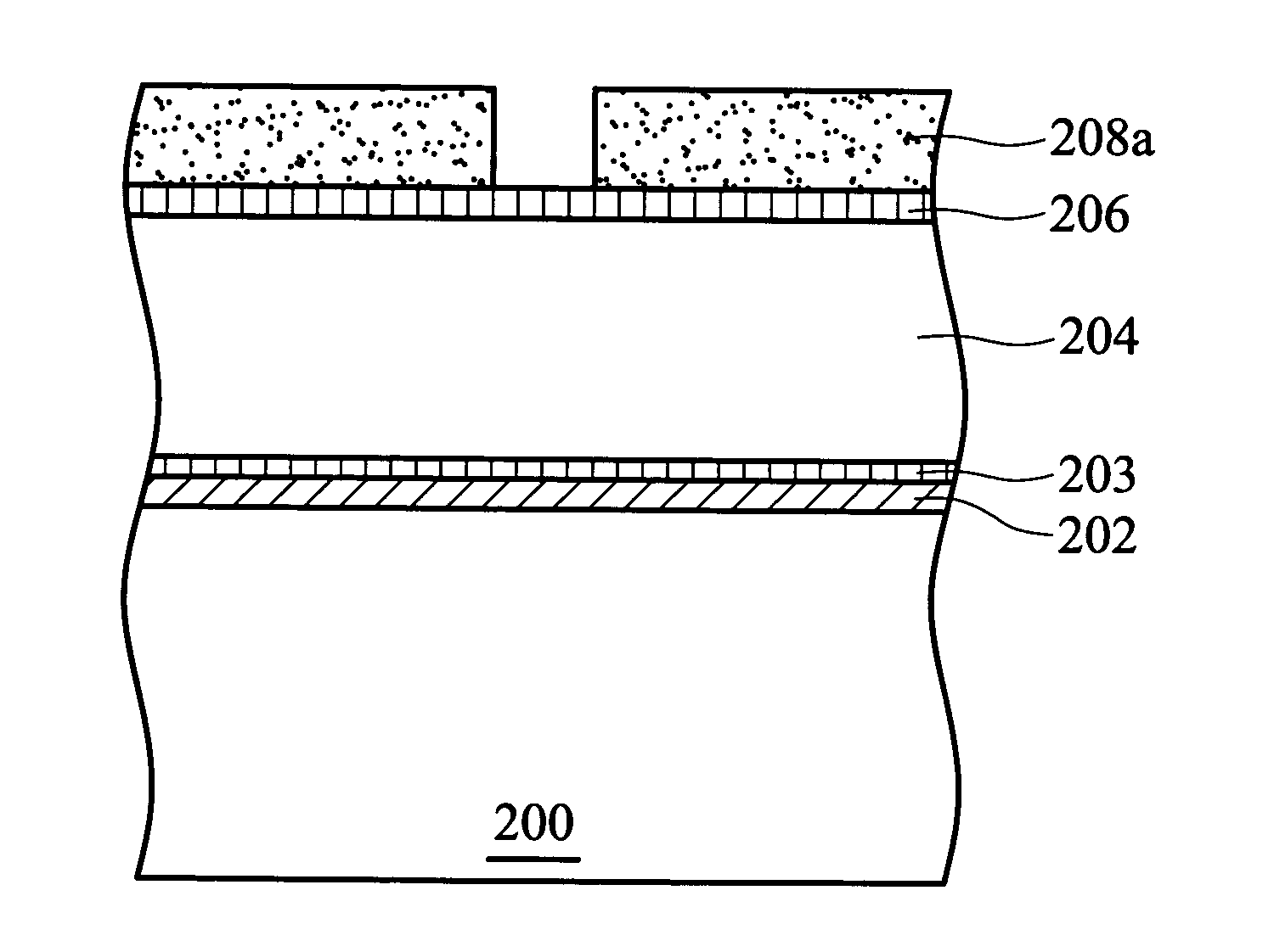
[0021]FIGS. 2a to 2e are cross-sections illustrating the method flow of preventing formation of photoresist scum according to the present invention.

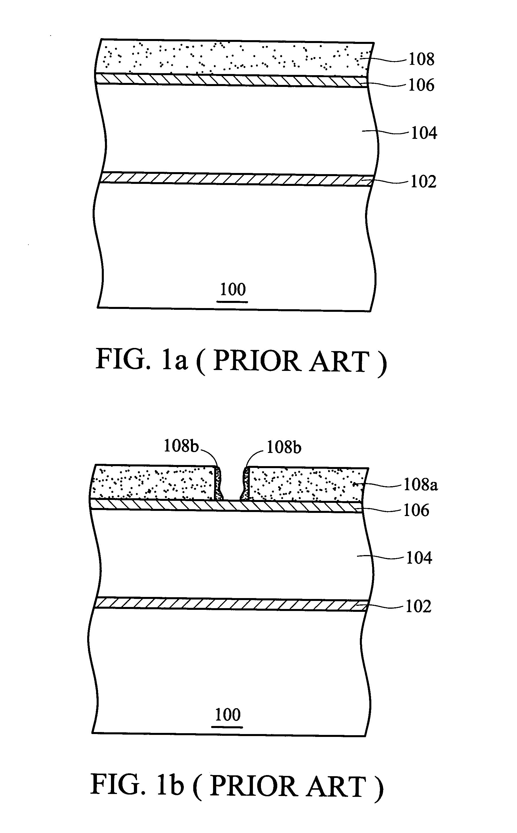
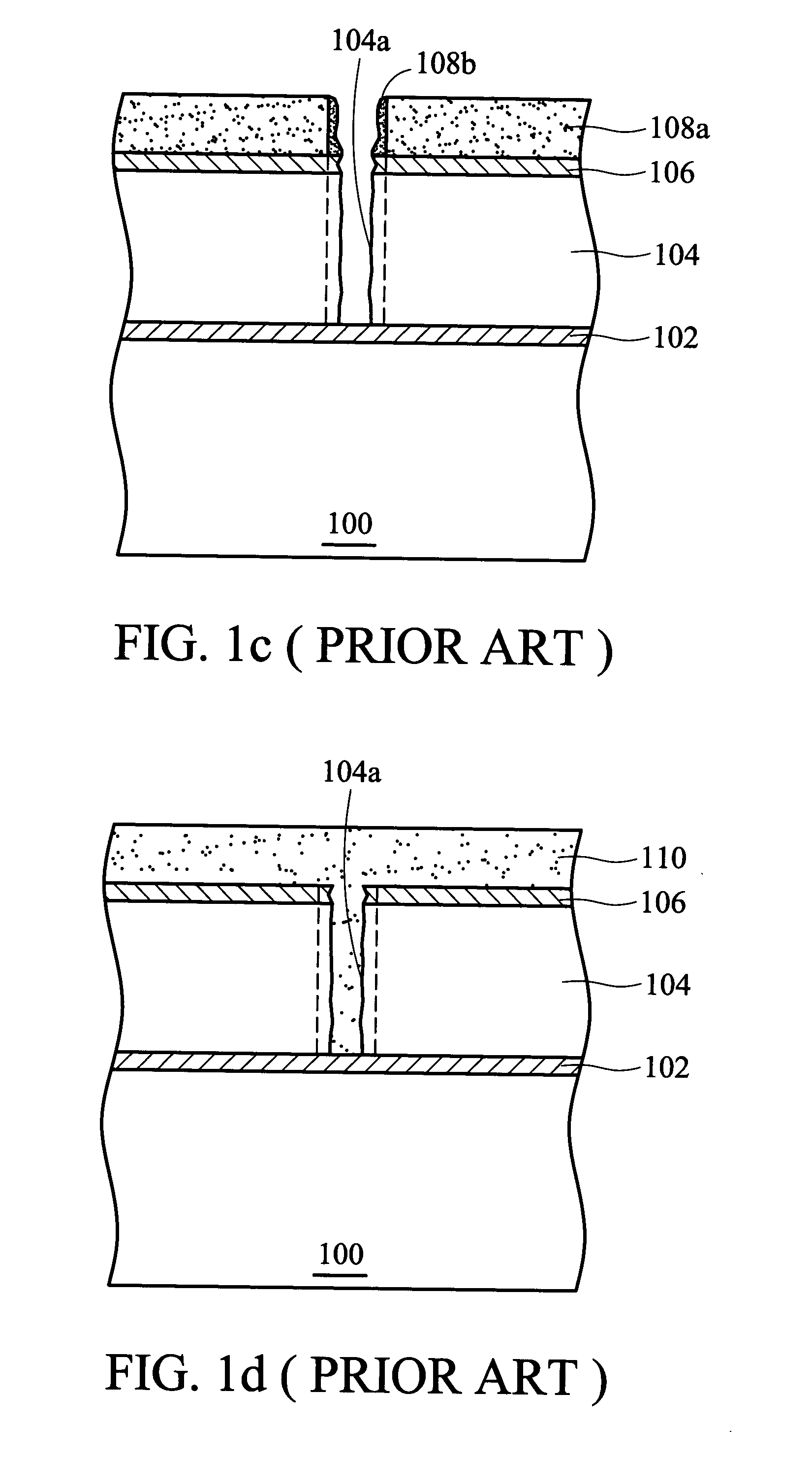
[0022] First, in FIG. 2a, a substrate 200 such as a silicon wafer is provided. Although there are semiconductor devices formed on the substrate 200, a flat substrate is depicted for simplicity. Next, an etching stop layer 202, a barrier layer 203, and a dielectric layer 204 are successively formed on the substrate 200. The material of the etching stop layer 202 can constitute silicon nitride or silicon carbon nitride. The barrier layer 203 can comprise silicon-rich oxide (SiOx) or hydrocarbon-containing silicon-rich oxide (SiOxCy:H), where x202 from diffusing into the dielectric layer 204. In addition, in the present embodiment, the etching stop layer 202 can also use material containing no nitrogen, such as silicon-rich oxide (SiOx) or hydrocarbon-containing silicon-rich oxide (SiOxCy:H) where x203. Next, a non-nitrogen anti-reflective ...

second embodiment

[0027]FIGS. 3a to 3e are cross-sections illustrating the method flow of preventing formation of photoresist scum according to the present invention.

[0028] First, in FIG. 3a, a substrate 300, such as a silicon wafer is provided. Next, an etching stop layer 302, a barrier layer 303, a dielectric layer 304, a barrier layer 305, an anti-reflective layer 306, and a photoresist layer 308 are formed on the substrate 300 in sequence. The etching stop layer 302 can comprise silicon nitride or silicon carbon nitride. The anti-reflective layer 306 can be silicon oxynitride. The barrier layers 305 and 303 can comprise silicon-rich oxide (SiOx) or hydrocarbon-containing silicon-rich oxide (SiOxCy:H), where x302 and in the anti-reflective layer 306 from diffusing into the dielectric layer 304.

[0029] Subsequently, in FIG. 3b, a photoresist pattern layer 308a is formed using conventional exposure and wet development procedures. Next, in FIG. 3c, the anti-reflective layer 306, the barrier layer 305...


PUM

PropertyMeasurementUnit
dielectricaaaaaaaaaa
thicknessaaaaaaaaaa
electrical propertiesaaaaaaaaaa

Abstract

A method for preventing formation of photoresist scum. First, a substrate on which a dielectric layer is formed is provided. Next, a non-nitrogen anti-reflective layer is formed on the dielectric layer. Finally, a photoresist pattern layer is formed on the non-nitrogen anti-reflective layer. During the formation of the photoresist pattern layer, the non-nitrogen anti-reflective layer does not react with the photoresist pattern layer, thus not forming photoresist scum. This prevents undesired etching profile and critical dimension (CD) change due to presence of photoresist scum. The non-nitrogen anti-reflective layer can be silicon-rich oxide (SiOx) or hydrocarbon-containing silicon-rich oxide (SiOxCy:H).

Description

BACKGROUND OF THE INVENTION [0001] 1. Field of the Invention [0002] The invention relates to a semiconductor process, and more particularly to a method for preventing formation of photoresist scum in order to improve etching profile and prevent clogging of via holes, thus improving subsequent metallization. [0003] 2. Description of the Related Art [0004] In current semiconductor integrated circuit method, the photolithography technique is a very critical procedure, in which accurate transfer of the circuit design to the semiconductor substrate determines the product properties. Generally, photolithography technique includes coating, exposure, development, and photoresist stripping. In recent years, with continuous miniaturization in device size, photolithography techniques require improvement and play an even more critical role in device quality, yield, and cost. [0005] In the dual damascene photolithography method, nitrogen (N) reacts with and contaminates the photoresist. Thus, du...

Claims


Application Information

Patent Timeline
Patent Type & Authority Applications(United States)
IPC IPC(8): C23F1/00G03F7/09
CPCY10S438/95G03F7/091
Inventor BAO, TIEN-IJENG, SHWANG-MINJANG, SYUN-MING
Owner TSMC CHINA COMPANY
Features
  • R&D
  • Intellectual Property
  • Life Sciences
  • Materials
  • Tech Scout
  • Unparalleled Data Quality
  • Higher Quality Content
  • 60% Fewer Hallucinations
Learn More