Microfabricated biopolymer scaffolds and method of making same

a biopolymer and micro-fabricated technology, applied in the field of micro-fabricated biopolymer scaffolds and the same making method, can solve the problems of complex objects, lack of organization of scaffolds, and inability to create most tissues, and achieve rapid micro-fabrication of scaffolds and iterative experimentation

Active Publication Date: 2005-01-13
RGT UNIV OF CALIFORNIA
View PDF21 Cites 72 Cited by
  • Summary
  • Abstract
  • Description
  • Claims
  • Application Information

AI Technical Summary

Benefits of technology

[0007] The invention is a series of soft lithography microfabrication methods for the generation of two-and three-dimensional polymer scaffolds. These methods present a wide range of possibilities to construct scaffolds with the desired characteristics according to the final application. The methods utilize a mold comprised of a polymeric material, preferably a silicone elastomer, (e.g. those described in U.S. Pat. No. 5,776,748, incorporated herein by reference) cast on a silicon master. The silicon master is generated by patterning of thick photoresist SU-8 (TM) directly with light through an inexpensive transparency and requires no reactive ion etching. The silicon elastomer mold is used as a template on which the polymer (e.g. those described in U.S. Pat. No. 6,160,084, incorporated herein by reference ) scaffold is cast. The silicon elastomer ...

Problems solved by technology

Material microstructure was first controlled by process parameters such as the choice of solvent in phase separation, doping with particulate leachants, gas foaming, woven fibers, and controlled ice crystal formation and subsequent freeze-drying to create pores; however, these scaffolds lack a well-defined organization that is found in most tis...

Method used


Image

  • Microfabricated biopolymer scaffolds and method of making same
  • Microfabricated biopolymer scaffolds and method of making same
  • Microfabricated biopolymer scaffolds and method of making same

Examples


example 1

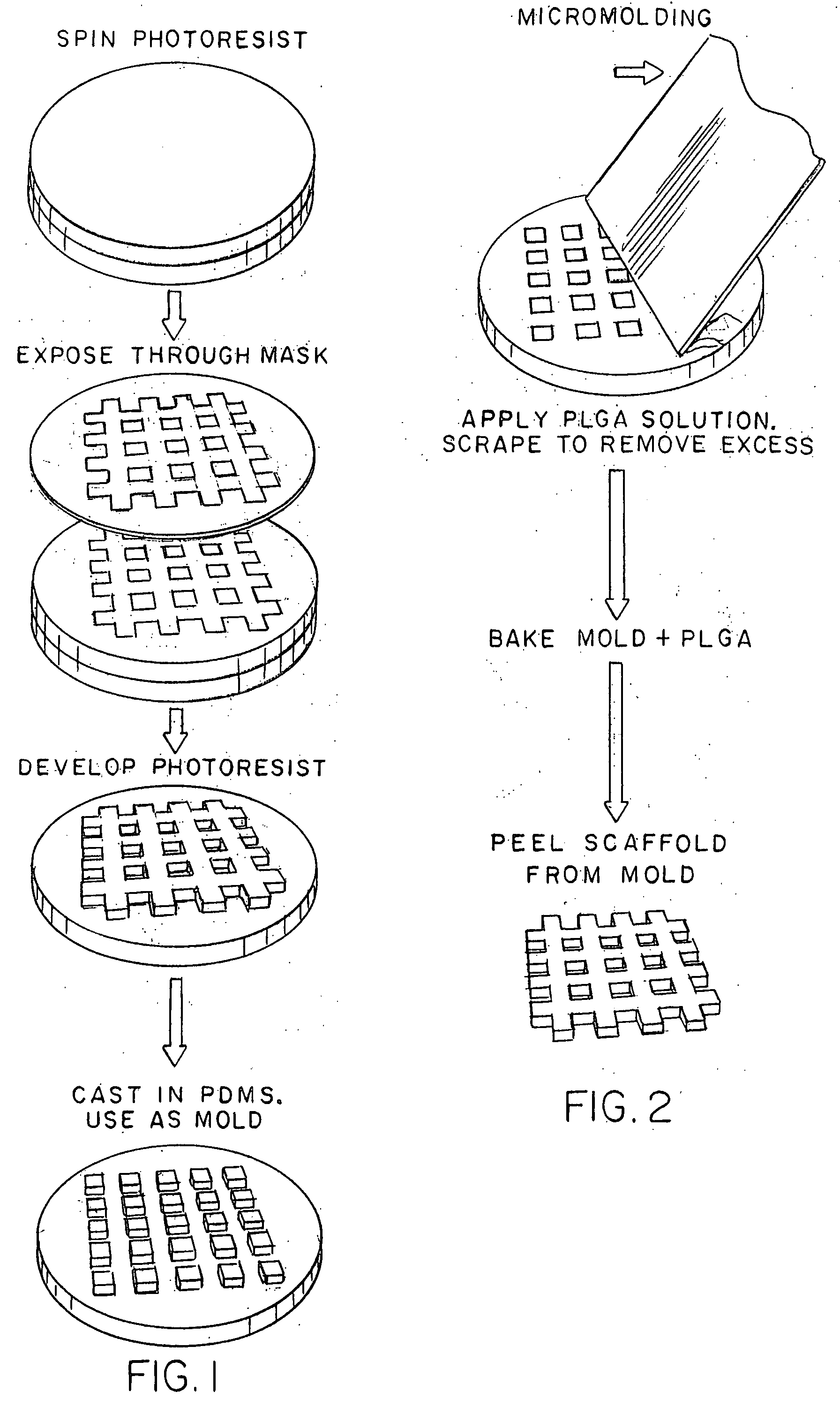
[0040] Micromolding of PLGA scaffolds. The micromolding technique is essentially solvent-casting on a PDMS mold. Many PLGA scaffolds can be produced with a single PDMS mold. The thickness of the resulting PLGA scaffold is determined by the height of the features on the photolithographic master (˜30 microns in this example) and by the concentration of polymer in the solution. The feature height on the master can in principle be a few microns. However, thin membranes are fragile and are difficult to manipulate manually. It was empirically noted that scaffold heights of greater than ˜30 microns yielded a scaffold with sufficient integrity to manipulate. The optimal PLGA concentration for use with this method was found to be around 10%-15%. At this concentration, the viscosity is high enough (around 100 cp) to allow the polymer solution to permeate the trenches of the PDMS mold when placed under vacuum. It was also observed that the solvent caused the PDMS mold to swell slightly. This l...

example 2

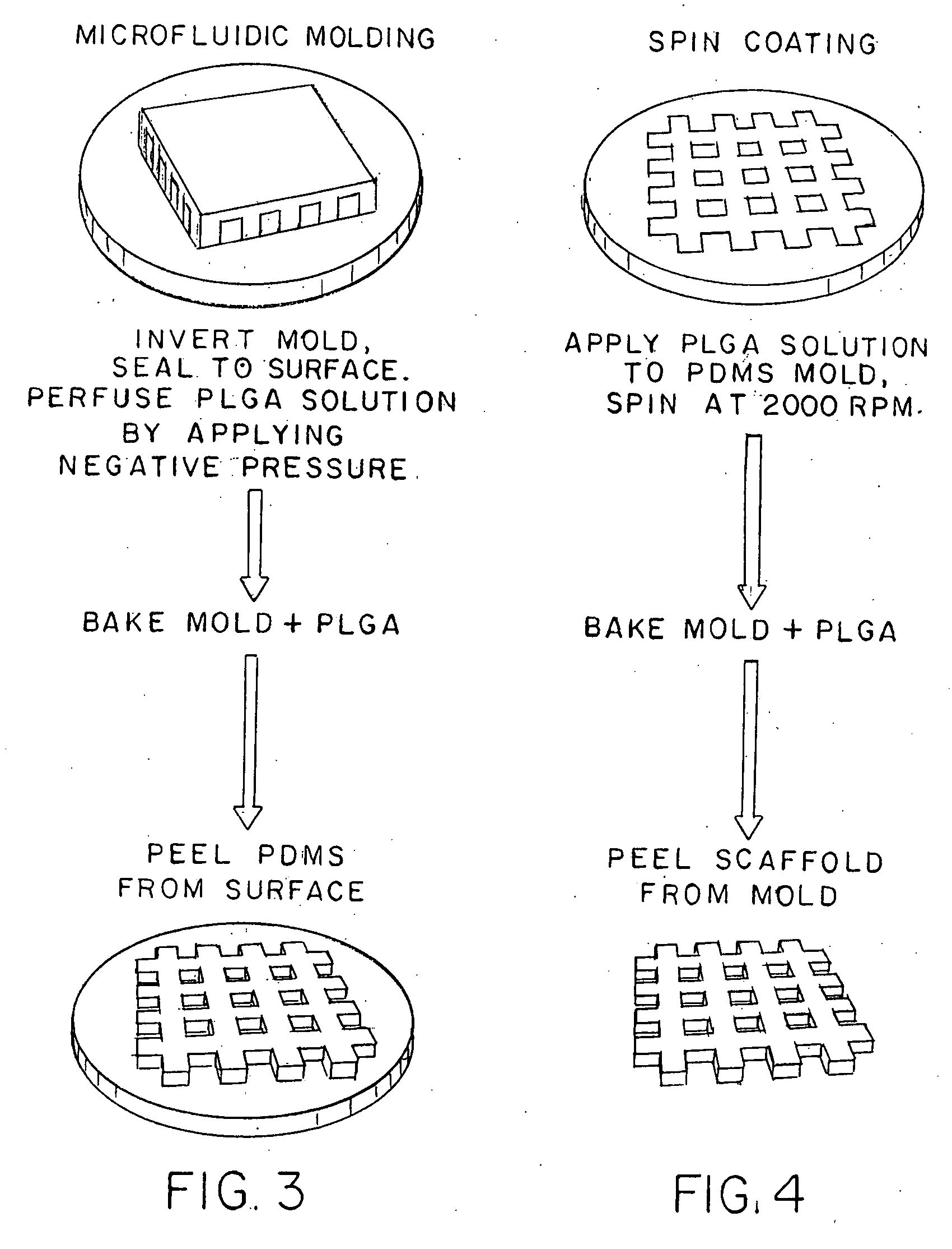
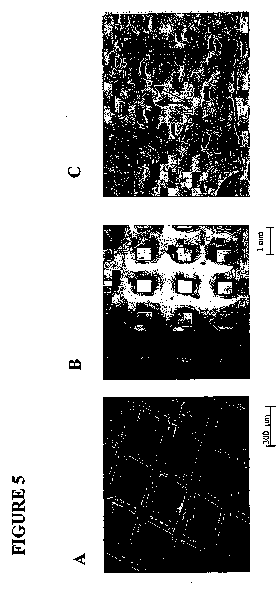
[0041] Microfluidic molding. The second variation was based on microfluidic flow. This technique took advantage of the microchannels created when a PDMS mold was reversibly sealed to a substrate. Microchannels were filled with a PLGA solution by application of negative pressure. In theory, the resolution of this technique is only limited by the resolution of the PDMS mold and hence the master. Practically, we found it difficult to mold patterns with small channel dimensions because the negative pressure that must be applied to fill the channels was excessive. Once the PLGA was cured, the PDMS was carefully removed to avoid damaging the thin structures. The average height of the scaffolds we fabricated was 10 microns. An typical scaffold obtained using this technique is shown in FIG. 5B. Unlike the other methods, microfluidic patterning could not be used to fabricate three dimensional structures because the polymer solution adhered strongly to the underlying substrate and could not b...

example 3

[0042] Spin coating. This method utilized a photoresist spin-coater to create a polymer layer that was thinner than the features on the master. A 5% PLGA solution was optimal for this method because the time required to fill the mold was compatible with the spinning time (˜30 seconds). Highly viscous solutions did not completely fill the mold because the solvent evaporated during spinning before the polymer solution could permeate the PDMS structure. With a fixed polymer concentration, the height of the scaffold can be regulated by varying the spinning speed. Typically, a speed of 2000 rpm yielded membranes with an average height of 7 microns. A typical scaffold produced using this method is shown in FIG. 5C. Meniscus effects were observed in regions where the polymer was in contact with the hydrophobic PDMS mold, producing non-uniform scaffold heights. Additionally small holes were observed on the membrane surfaces and hypothesize that bubbles were introduced through rapid solvent ...


PUM

PropertyMeasurementUnit
Timeaaaaaaaaaa
Pressureaaaaaaaaaa
Structureaaaaaaaaaa

Abstract

The invention is a series of soft lithographic methods for the microfabrication of biopoilymer scaffolds for use in tissue engineering and the development of artificial organs. The methods present a wide range of possibilities to construct two- and three-dimensional scaffolds with desired characteristics according to the final application. The methods utilize an elastomer mold which the biopolymer scaffold is cast. The methods allow for the rapid and inexpensive production of biopolymer scaffolds with limited specialized equipment and user expertise.

Description

CROSS-REFERENCES TO RELATED APPLICATIONS [0001] This application claims the benefit of priority of U.S. provisional application Ser. No. 60 / 302,879 filed Jul. 3, 2001 which is incorporated herein by reference in its entirety.GOVERNMENT INTEREST [0002] The invention was made with government support from the National Institutes of Health under grant number 5 RO1 DK56966-02.BACKGROUND OF THE INVENTION [0003] Tissue engineering describes an attempt to create tissues that repair or replace damaged tissues, typically by combining the use of biomaterials and cells. Control of polymer scaffold architecture is of fundamental importance in tissue engineering A wide variety of techniques for controlling the architecture of biomaterials are already available for relatively large feature sizes of the order of millimeters to centimeters. These include polymer extrusion, solution casting and particulate leaching, deposition of a polymer solution stream on a spinning mandrel and manipulation of she...

Claims


Application Information

Patent Timeline
IPC IPC(8): B29C67/20
CPCY10T428/24322B29C67/202Y10T428/26Y10T428/269Y10T428/24273A61F2/00
Inventor BHATIA, SANGEETA N.VOZZI, GIOVANNI
Owner RGT UNIV OF CALIFORNIA
Why Eureka
Try Eureka