Sputtering target assemblies using resistance welding

Active Publication Date: 2005-01-20
GLOBAL ADVANCED METALS USA
View PDF14 Cites 41 Cited by
  • Summary
  • Abstract
  • Description
  • Claims
  • Application Information

AI Technical Summary

Benefits of technology

[0005] A feature of the present invention is to provide a method of forming a sputtering target assembly

Problems solved by technology

However, sputtering target assemblies bonded by methods at high temperatures can warp the assembly during use which affects performance of the sputtering target assembly, especially when a large difference exists between the coefficients of thermal expansion for the target and the backing plate.
Moreover, the differential thermal expansion between the target material and the backing plate material which occurs when bonding is accomplished at elevated temperatures by soldering, brazing, or diffus

Method used


Image

  • Sputtering target assemblies using resistance welding
  • Sputtering target assemblies using resistance welding
  • Sputtering target assemblies using resistance welding

Examples


Embodiment Construction

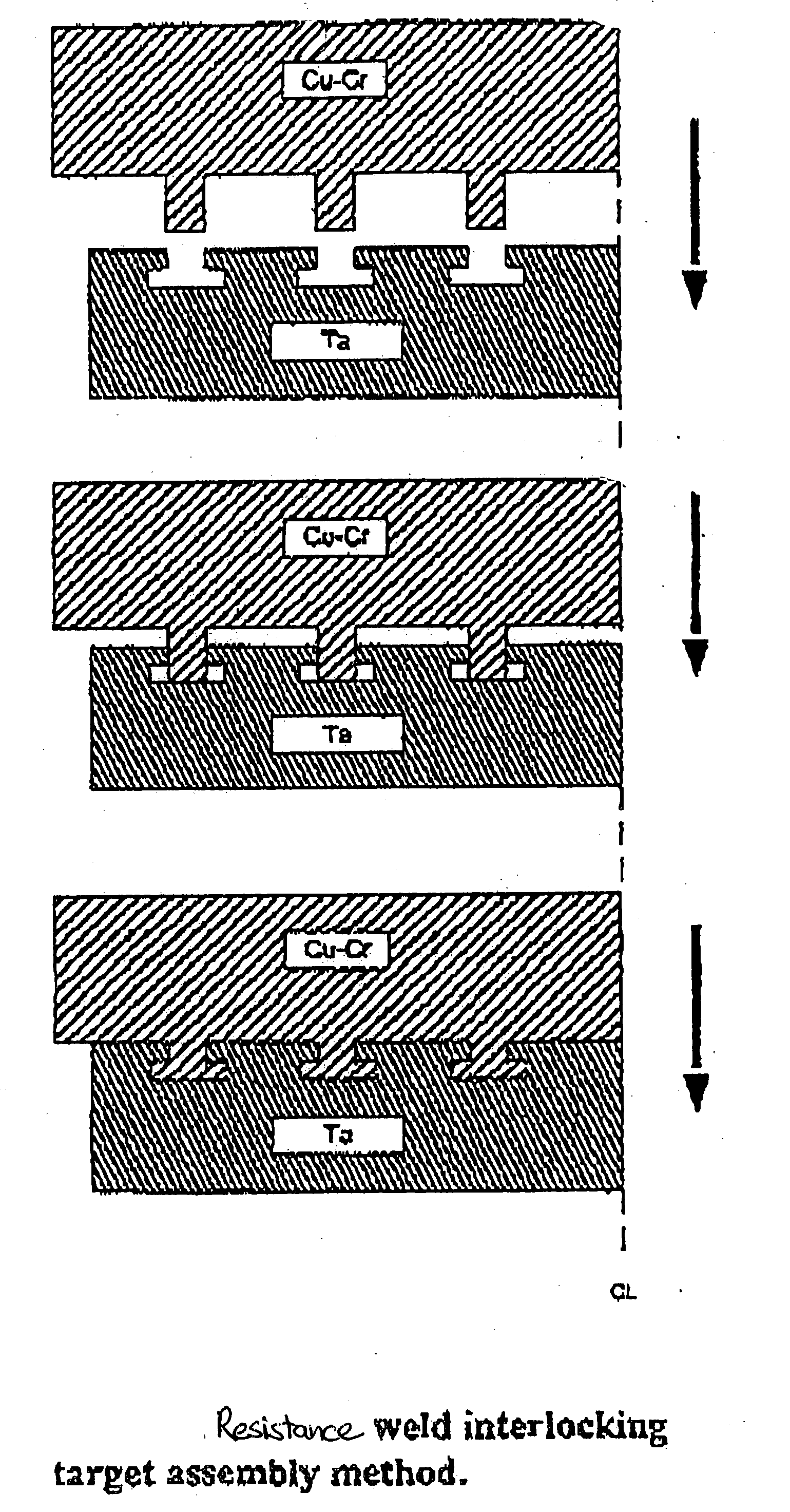
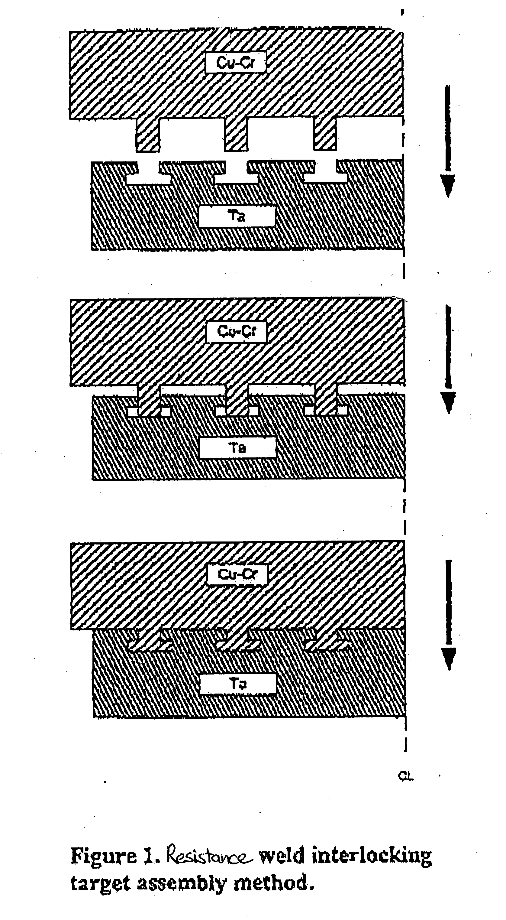
[0020] The present invention relates to a method of assembling a sputtering target assembly or other metal article by a bonding process that includes fixing a sputter target or other metal to a backing plate or other metal, preferably at a low temperature. The method includes contacting a portion of at least one projection on a bonding side of a first assembly member having a plurality of projections, against a portion of a groove on a bonding side of a second assembly member having a plurality of grooves; contacting a first electrode to one of the assembly members, and a second electrode to the other assembly member; conducting an electric current through the electrodes to cause resistance heating of the at least one projection and the groove; and partially deforming the at least one projection to a least partially fill the groove by applying a force between the projection and the groove, thereby forming at least a mechanical bond between the assembly members.

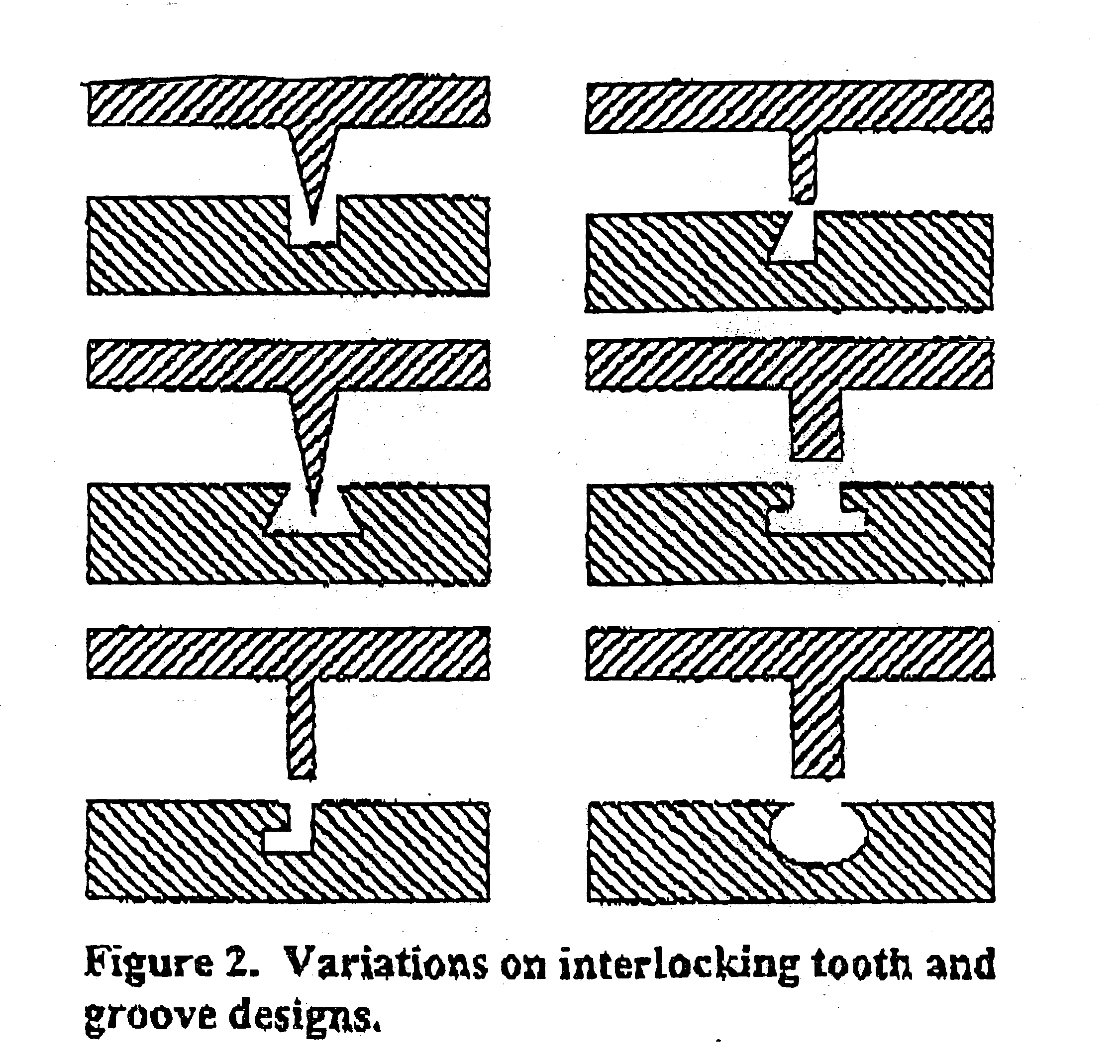
[0021] Preferably, th...


PUM

PropertyMeasurementUnit
Pressureaaaaaaaaaa
Pressureaaaaaaaaaa
Pressureaaaaaaaaaa

Abstract

A method of forming a sputtering target assembly and other metal articles is described. Sputtering target assemblies and metal articles are also described. The method includes bonding a sputter target to a backing plate using resistance heating or welding to bond assembly members that respectively include mating projections and grooves formed in bonding surfaces thereof.

Description

BACKGROUND OF THE INVENTION [0001] The present invention relates to sputtering target assemblies and other metal articles, as well as methods of making the same. More particularly, the present invention relates to methods to bond various metals together to form bonded sputtering target assemblies and other bonded articles, preferably at a low temperature. [0002] In the sputter application field, typically a sputtering target assembly has a sputter target and a backing plate. For instance, a metal target or metal target blank (e.g., tantalum, titanium, aluminum, copper, cobalt, tungsten, etc.) is bonded onto a backing plate, such as a backing plate flange assembly such as copper, aluminum, or alloys thereof. To achieve good thermal and electrical contact between the target and the backing plate, these members are commonly attached to each other by means of soldering, brazing, diffusion bonding, clamping, and by epoxy cement and the like. However, sputtering target assemblies bonded b...

Claims


Application Information

Patent Timeline
IPC IPC(8): C23C14/34H01J37/34
CPCH01J37/3435C23C14/3407
Inventor KACHALOV, MIKHAIL Y.WICKERSHAM, CHARLES E. JR.
Owner GLOBAL ADVANCED METALS USA
Why Eureka
Try Eureka