Monolithic photoreceiver technology for free space optical networks

a free space optical network and photoreceiver technology, applied in the direction of nanoinformatics, semiconductor lasers, radiocontrolled devices, etc., can solve the problems of ineffective cost reduction, inability to increase the link budget, and inability to achieve the effect of optimizing the design and performance of monolithic photoreceivers

Inactive Publication Date: 2005-01-20
EPITAXIAL TECH
View PDF7 Cites 16 Cited by
  • Summary
  • Abstract
  • Description
  • Claims
  • Application Information

AI Technical Summary

Benefits of technology

An object of the present invention is to implement a compact monolithic photoreceiver that is capable of near quantum limit sensitivities operating with a BER of 10−9 up to 40 Gb / s bit rate. Another object of the present invention is to implement a compact monolithic photoreceiver that is capable of −47 dBm sensitivity operating with a BER of 10−9 at 2.5 Gb / s bit rate. Another object of this invention is to optimize the design and performance of a monolithic phototranceiver.

Problems solved by technology

The main disadvantage of FSO is atmospheric attenuation, which is weather dependent.
Therefore, in order to address the atmospheric attenuation either link distance or link budget has to be compromised.
Increasing the link budget will not be cost effective and also increases the size, weight and power (SWaP).
Although there have reportedly been bench level demonstrations of direct detection photo-receivers employing erbium doped fiber amplifier (EDFA) technology that have comparable performance, there are no compact, affordable, and commercially available photo-receivers that will meet these requirements(2,3).

Method used


Image

  • Monolithic photoreceiver technology for free space optical networks
  • Monolithic photoreceiver technology for free space optical networks
  • Monolithic photoreceiver technology for free space optical networks

Examples


Embodiment Construction

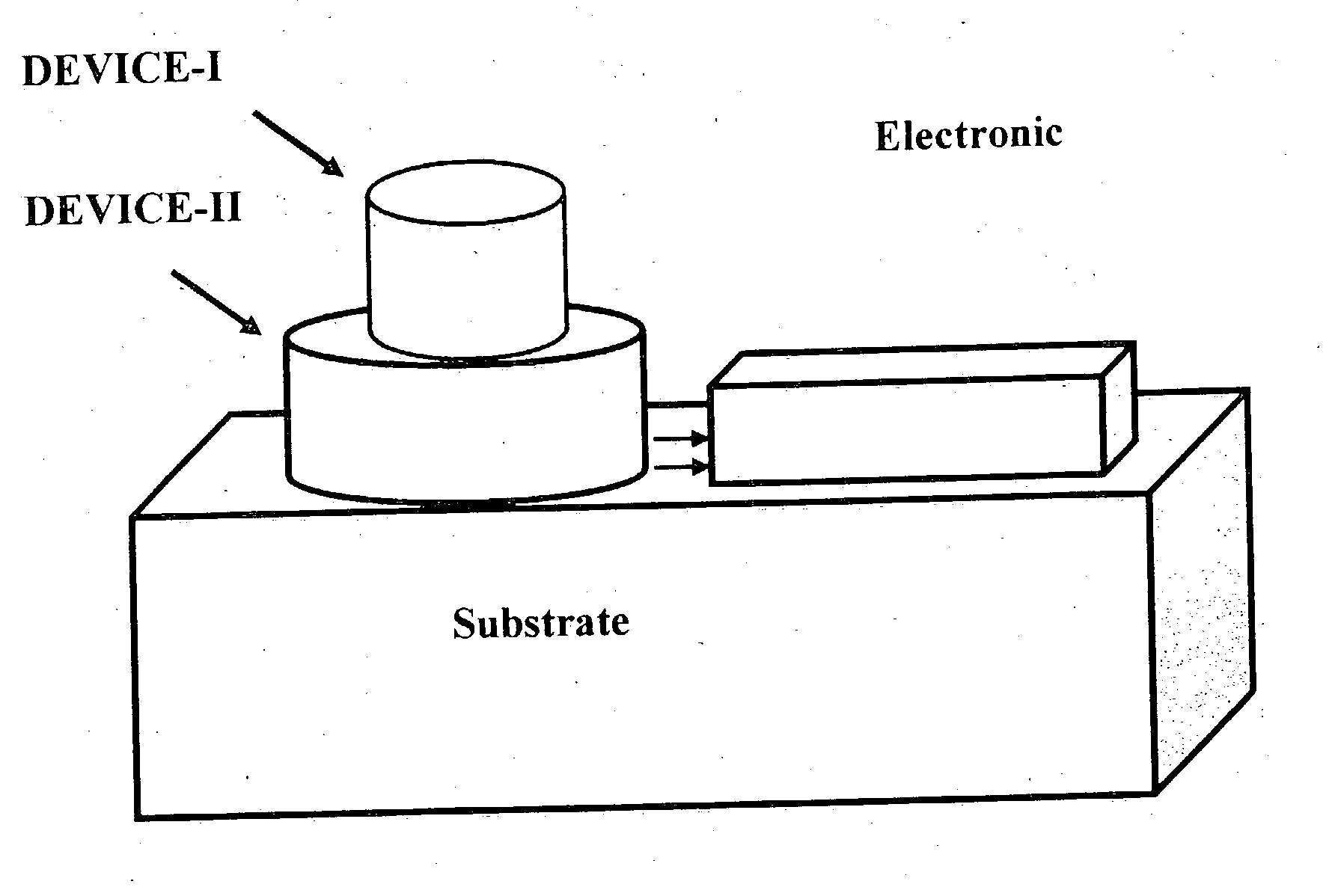
In the following sections, we present the concept and design of the photoreceiver, showing performance variations with design parameters. We also present performance achieved thus far and the expected performance when the monolithic photoreceiver is optimized.

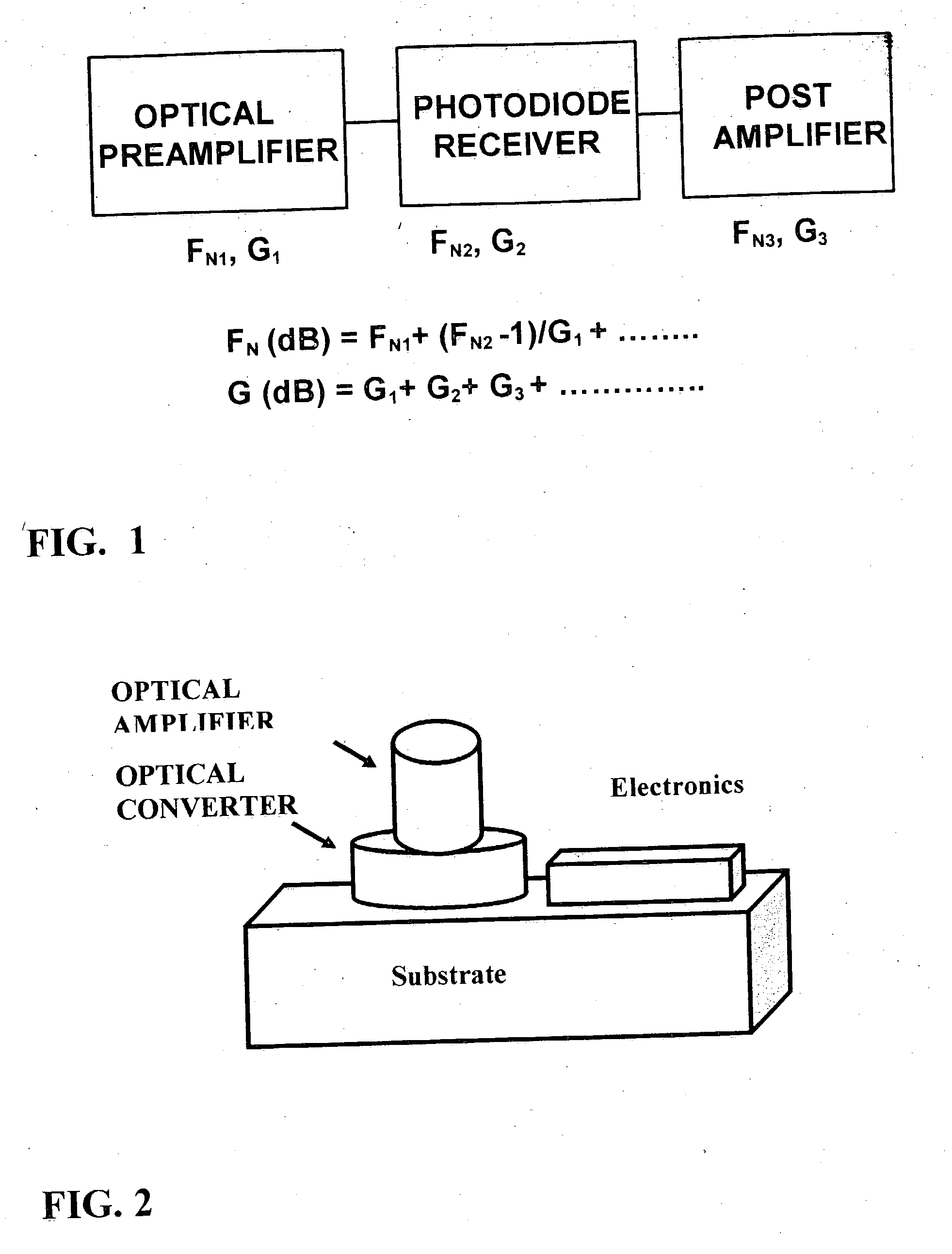
(1) Photoreceiver Concept:

The concept of pre-amplified photoreceivers is well established, having been applied to produce the most sensitive optical receivers to date. Its effectiveness is based on the fact that when amplifiers are cascaded as shown in FIG. 1, the gain is additive, while the noise figure depends directly on the noise figure and inversely as the gain of the 1st stage. This provides maximum flexibility in designing ultra low noise photoreceivers since the front end (1st stage) can be optimized for minimum noise performance which also translates into-moderate gain. Subsequent stages can then be optimized for high gain to achieve the required sensitivity requirements. With this approach, near quantum limit sen...


PUM


Abstract

This invention describes an approach for monolithically integrating all the components of a photoreceiver—optical amplifier, optical band-pass filter, and photodiode module—in a single chip. The photoreceiver array employs unique optical amplifier and conversion technologies that provides the ultra-sensitivity required for free space optical communications networks. As an example, by monolithically integrating a vertical cavity surface emitting laser-diode (VCSEL) optical preamplifier with a photodiode receiver and related amplifiers and filters on the same chip, sensitivities as low as −47 dBm (62 photons/bit at 2.5 Gb/s), along with an order of magnitude reduction in size, weight, and power consumption over comparable commercial-off-the-shelf (COTS) components can be demonstrated. In accordance with another aspect of the present invention, the concept of monolithic integration of optical amplifier with photodetector is extended to lasers, another amplifier and modulators covering ultra violet to very long wavelength infrared using the InP, GaAs, GaSb, InAs, InSb, SiGe, SiC and GaN etc based technologies.

Description

BACKGROUND OF THE INVENTION (1) Field of the Invention The present invention relates to monolithic photoreceiver technology. (2) Brief Description of Related Art The next logical extension to the Internet is a free space mobile digital data network that is pervasive and can meet both commercial telecommunications' need for ubiquitous connectivity and need to provide the war-fighters with assured and secure information anywhere, at any time, and in the right form, using an extensible communication architecture that assures maximum connectivity among the current terrestrial networks, the battlefield, aircraft, spacecraft, Unmanned Vehicles (UAVs), ships and submarines. Of all the candidate technologies, free space mobile optical communications is considered the most likely to enable the highest data rate, longest range and highest sensitivity. To achieve connectivity to other terminals in the theater and the needed bit rate of greater than 2.5 Gb / s, the notional free space mobile...

Claims


Application Information

Patent Timeline
Patent Type & Authority Applications(United States)
IPC IPC(8): H01L33/00
CPCB82Y10/00H01L27/1446H01L29/7376H01S5/50H01S5/02248H01S5/18305H01S5/423H01S5/0014H01S5/02325
Inventor FATHIMULLA, AYUB M.AINA, OLALEYE A.HIER, HARRY STEPHEN
Owner EPITAXIAL TECH
Why Eureka
Try Eureka