Plant control system

Active Publication Date: 2005-01-20
HONDA MOTOR CO LTD
View PDF6 Cites 9 Cited by
  • Summary
  • Abstract
  • Description
  • Claims
  • Application Information

AI Technical Summary

Benefits of technology

With this arrangement, when an output of the actuator changes to compensate for friction that changes with the cam phase angle or a spring reaction force if a mechanism for returning the cam has a spring, the disturbance predictor determines, as the predicted value of disturbance, a manipulated variable for the actuator on the basis of the cam phase angl

Problems solved by technology

However, correcting model parameters on the basis of identification errors, as described above, has been making it impossible to accomplish adequat

Method used


Image

  • Plant control system
  • Plant control system
  • Plant control system

Examples


Example

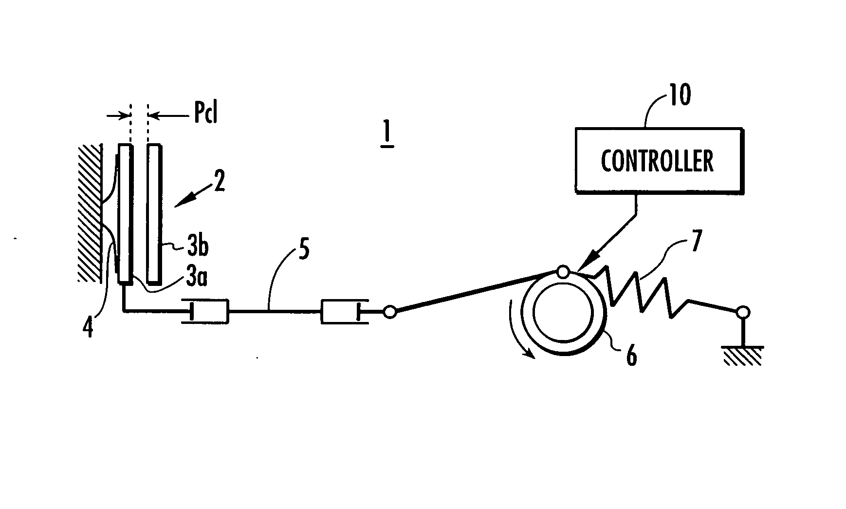
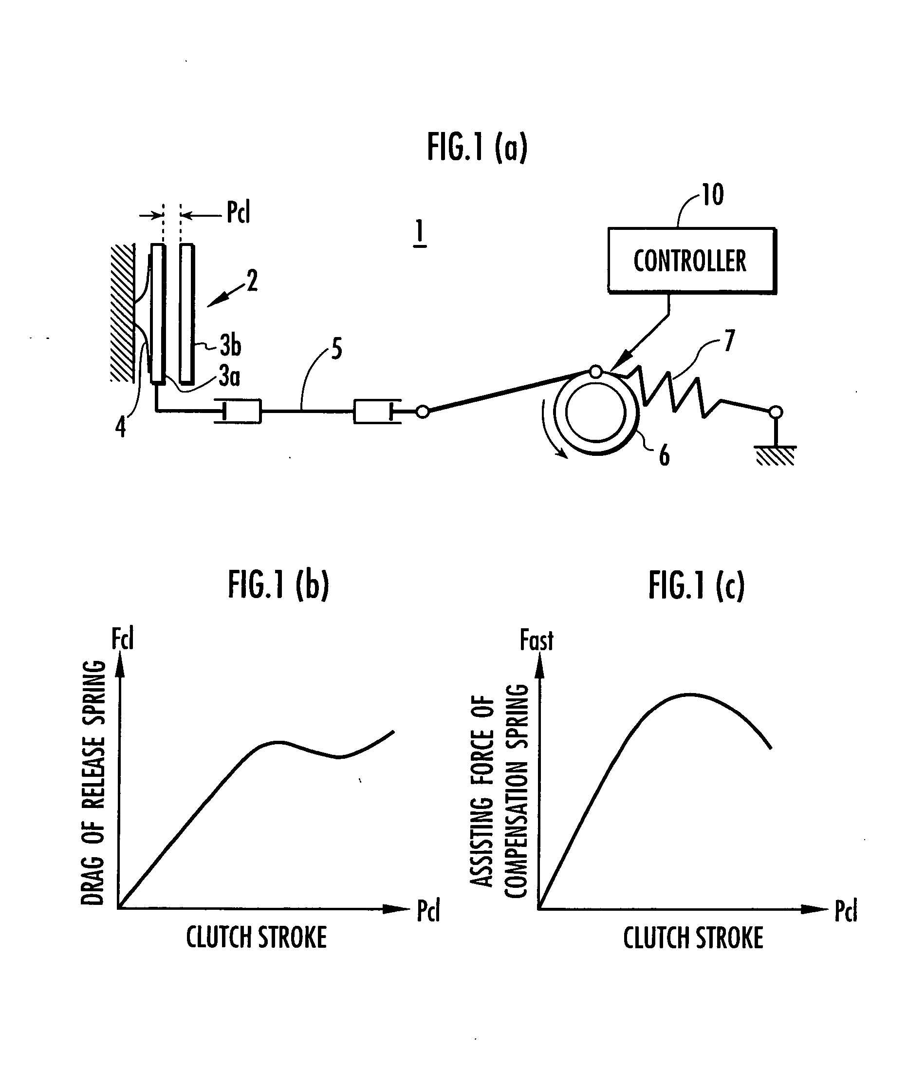
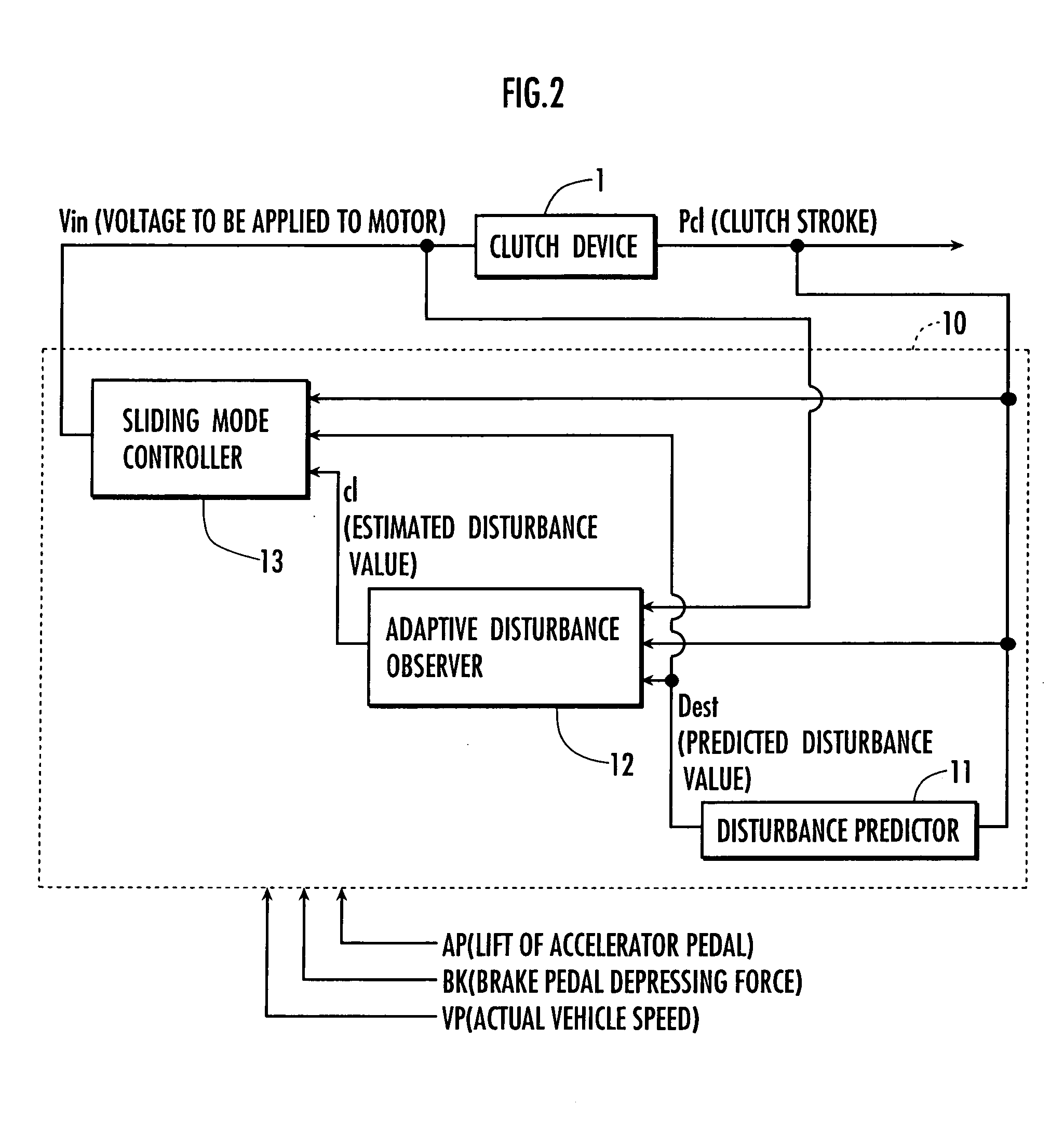
Referring to FIG. 1 through FIG. 12, an embodiment of the present invention will be described. FIG. 1 includes a configuration diagram of a clutch mechanism and an explanatory diagram showing an elastic member in operation, the elastic member being provided in the clutch mechanism. FIG. 2 is a block diagram showing control carried out by a controller of the clutch mechanism shown in FIG. 1. FIG. 3 shows charts of simulation results obtained when the controller is provided with an adaptive disturbance observer. FIG. 4 through FIG. 8 are operation flowcharts of the controller shown in FIG. 2. FIG. 9 is an explanatory diagram of a system in which the present invention has been applied to control of an engine speed. FIG. 10 and FIG. 11 are explanatory diagrams showing a system in which the present invention has been applied to phase angle control of a cam phase changing device of an engine.

Referring to FIG. 1A, a clutch apparatus 1 corresponding to a plant in accordance with the pres...


PUM


Abstract

A plant control system provides an enhanced capability of compensation for disturbance that abruptly changes. A controller includes a disturbance predictor for calculating a predicted value of disturbance on the basis of a drag force of a release spring and an assisting force of a compensation spring that are predicted on the basis of a clutch stroke, an adaptive disturbance observer for calculating an estimated value of disturbance on the basis of the estimated value of disturbance, a voltage to be applied to a motor, and the clutch stroke, and a sliding mode controller, which determines the voltage to be applied to the motor by carrying out control for making the clutch stroke follow a clutch stroke target value by determining the voltage to be applied to the motor by sliding mode control on the basis of the clutch stroke, the predicted value of disturbance, and the estimated value of disturbance.

Description

BACKGROUND OF THE INVENTION 1. Field of the Invention The present invention relates to a control system for controlling outputs of a plant to be controlled using response specifying control. 2. Description of the Related Art As a system for controlling outputs of a plant to be controlled using response specifying control, a throttle valve controller, for example, has been proposed. In this controller, the degree of opening of a throttle valve provided in an intake passage of an engine is adjusted by sliding mode control (refer to, for example, Japanese Laid-Open Patent Publication No. 2002-318605). According to the aforesaid throttle valve controller, model parameters in a model equation of a driving device of the throttle valve are corrected on the basis of identification errors (deviations from reference values of model parameters). This makes it possible to reduce influences of modeling errors or disturbance in determining a manipulated variable of the driving device of the ...

Claims


Application Information

Patent Timeline
IPC IPC(8): F02D11/10F02D13/02F02D31/00F02D41/14F16D48/02F16D48/06F16H61/02F16H61/08G05B5/01G05B13/02G05B13/04
CPCF02D31/002G05B2219/41432F02D41/1403F02D2041/001F16D48/064F16D2500/1024F16D2500/10412F16D2500/1045F16D2500/3026F16D2500/3108F16D2500/31426F16D2500/3144F16D2500/50293F16D2500/7041F16D2500/70631F16D2500/7087F16H61/0213F16H61/08G05B5/01G05B13/0255G05B13/026G05B13/04G05B2219/41214G05B2219/41333F02D41/1401F16D48/066F16D2500/30806F16D2500/5102F16D2500/70404F16D2500/7042F16D2500/70454F16D2500/70462
Inventor YASUI, YUJISHIMOJO, KANAKO
Owner HONDA MOTOR CO LTD
Why Eureka
Try Eureka