Soil-resistant coating for glass surfaces

a technology of glass surface and soot-resistant coating, which is applied in the direction of vacuum evaporation coating, coating, transportation and packaging, etc., can solve the problems of a large number of windows being cleaned, a large amount of time and expense, and a large amount of windows being cleaned

Inactive Publication Date: 2005-01-27
CARDINAL CG
View PDF99 Cites 31 Cited by
  • Summary
  • Abstract
  • Description
  • Claims
  • Application Information

AI Technical Summary

Benefits of technology

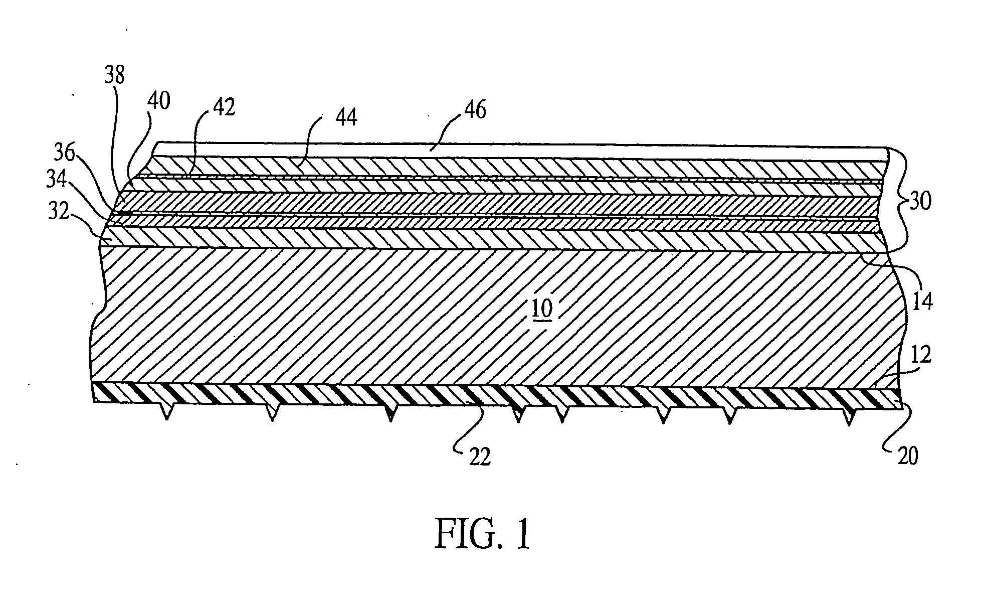
[0013] In one aspect, the present invention provides a glass article which has a water-sheeting coating and a method of applying such a coating. In accordance with a first embodiment of this invention, a glass article has at least one coated surface bearing a water-sheeting coating. This water-sheeting coating comprises silica sputtered directly onto an e

Problems solved by technology

Keeping windows and other glass surfaces clean is a relatively expensive, time-consuming process.
While cleaning any individual window is not terribly troublesome, keeping a larger number of windows clean can be a significant burden.
For example, with modern glass office towers, it takes significant time and expense to have window washers regularly clean the exterior surfaces of the windows.
First, the water itself can deposit or collect dirt, minerals or the like onto the surface of the glass.
Obviously, dirty water landing on the glass will leave the entrained or dissolved dirt on the glass upon drying.
Even if relatively clean water lands on the exterior surface of a window, each water droplet sitting on the window will tend to collect dust and other airborne particles as it dries.
As a result, the glass which underlies a drying water droplet will become a little bit rougher by the time the water droplet completely dries.
In storing and shipping plate glass, the presence of water on the surfaces between adjacent glass sheets is a chronic problem.
However, if the glass is stored in a humid environment, water can condense on the glass surface from the atmosphere.
This becomes more problematic when larger stacks of glass are collected.
Large stacks of glass have

Method used


Image

  • Soil-resistant coating for glass surfaces
  • Soil-resistant coating for glass surfaces
  • Soil-resistant coating for glass surfaces

Examples


experimental example 1

[0085] Both of the samples were subjected to a salt spray test in accordance with ASTM B117 using a 5% salt solution for 250 hours. Briefly, the samples were cleaned and placed in a Singleton SCCH #20 Corrosion Cabinet at an angle of about 15-30° from vertical, with Sample B being oriented such that the surface bearing the water-sheeting coating 20 was oriented to face downwardly. A 5% salt solution (5 wt % sodium chloride, 95 wt % distilled water) was atomized in the cabinet at about 35° C. for 250 hours, with the salt solution being collected at a rate of about 1.8 ml per 80 cm per hour in the collection cylinders in the cabinet. Thereafter, the samples were removed from the cabinet, rinsed, allowed to dry and visually inspected. Sample A had more numerous water spots than did Sample B and the water spots on Sample A were more visible than the light streaks on Sample B.

[0086] Each sample was then cleaned using paper towels and Windex®. The haze of each sample was then measured us...

experimental example 2

[0088] Handling the samples with tongs, each sample was first dipped in a beaker of boiling tap water maintained at about 100° C. and held there for about 5 seconds, after which it was deposited in a beaker of ice water maintained at about 0° C. and held there for about 5 seconds. This process was repeated 25 times. The samples were then placed in a Singleton Model SL23 humidity test chamber maintained at about 90% relative humidity at about 120° F. (about 49° C.) for about 500 hours. Each sample was then visually inspected. As in Experimental Example 1, it was determined that Sample A exhibited more numerous and more visible water spots than did Sample B.

[0089] Each sample was then cleaned and the haze and contact angle measurements were taken in much the same manner outlined above in Experimental Example 1. The haze measurement for Sample A was 0.34% while that for Sample B was 0.14%. Sample A exhibited a contact angle of about 20° while the contact angle for Sample B was about 1...

experimental example 3

[0090] Two samples of uncoated glass (Samples A1 and A2) and two samples of coated glass (Samples B1 and B2) were cleaned and their haze measurements were taken. Each of the uncoated samples had haze measurements of about 0.09% while the haze measurement for the glass with a water-sheeting coating 20 was about 0.08%.

[0091] A cement mixture was prepared by mixing 4 ounces (about 11.5 g) of portland cement to 1000 ml of water. Two samples of uncoated glass (Samples A1 and A2) and two samples of coated glass (Samples B1 and B2) were held in this solution for about ten minutes then removed. Samples A1 and B1 were then rinsed liberally with water (but without any rubbing) and allowed to dry; Samples A2 and B2 were allowed to air dry without rinsing.

[0092] All four samples were hand cleaned using Windex® and paper towels. The residual soiling on Samples A1 and A2 from the cement test smeared during this cleaning, making it more difficult to clean the glass. In contrast, neither Samples ...


PUM

PropertyMeasurementUnit
Thicknessaaaaaaaaaa

Abstract

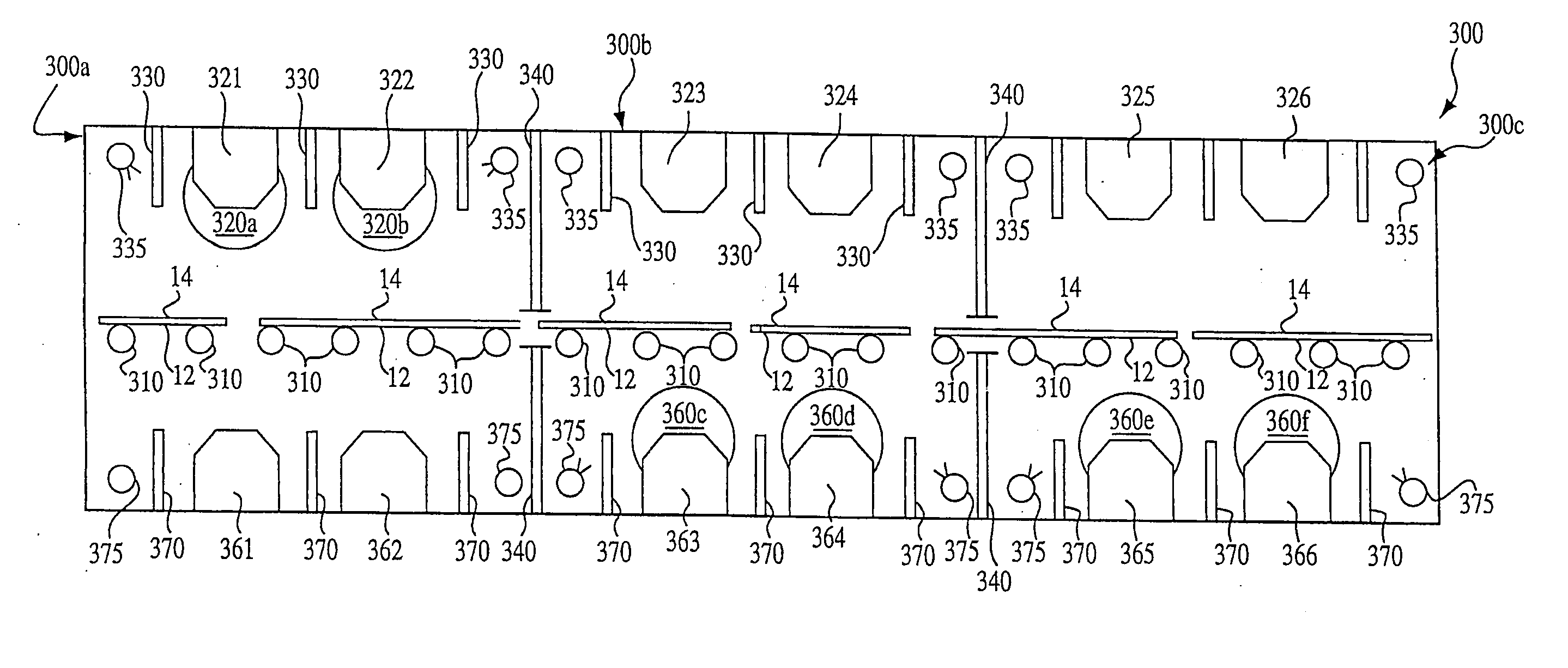
A method and apparatus for coating two sides of a single pane of glass or other substrate in a single pass through a coating apparatus. A sputtering line is provided, this line comprising a series of sputtering chambers. At least one of the chambers comprises a downward sputtering chamber having an upper target. At least one of the chambers comprises an upward sputtering chamber having a lower target. In some embodiments, the upper and lower targets are rotary targets. The coating apparatus advantageously has a plurality of transport rollers for conveying the substrate along the sputtering line. In certain embodiments, a majority of the chambers of the sputtering line are downward sputtering chambers each having only an upper target with no lower target.

Description

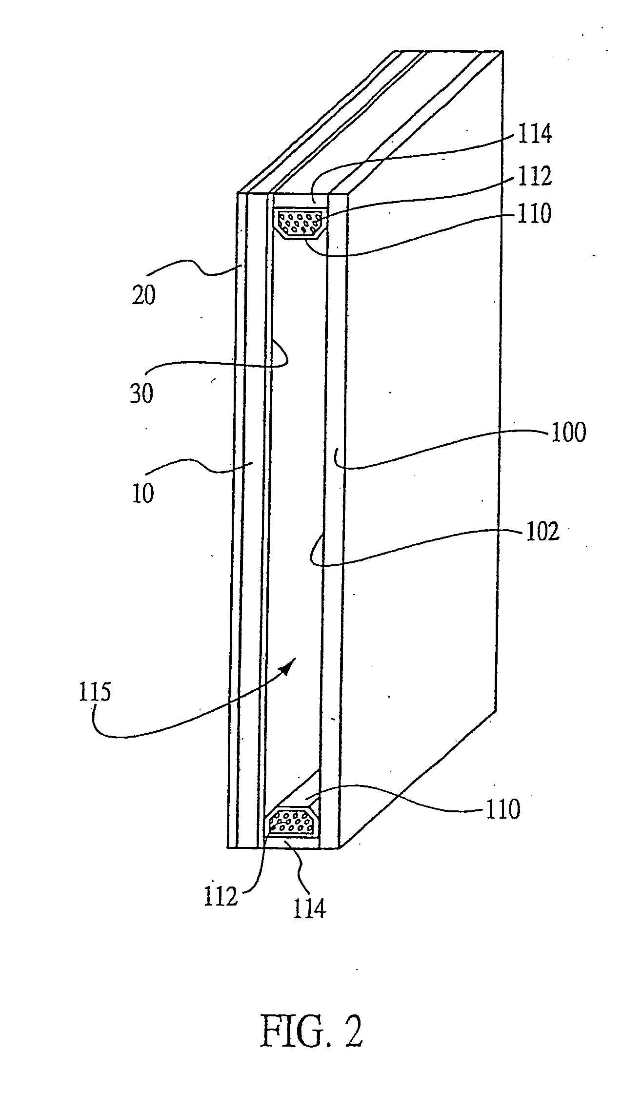
RELATED APPLICATIONS [0001] This is a divisional application of U.S. application Ser. No. 09 / 868,542, filed Feb. 2, 1999, which in turn is a national stage application based on PCT US99 / 02208, filed Feb. 2, 1999, which in turn claims priority to U.S. Application No. 60 / 113,259, filed Dec. 21, 1998, all of which are incorporated herein by reference.FIELD OF THE INVENTION [0002] The present invention provides a coating for glass substrates and the like which resists accumulation of dirt and water stains. Coated glass substrates of the invention can be used in insulated glass units wherein the coating of the invention is carried on an exterior surface of one pane of glass while a reflective coating is applied on the opposite side of the same pane of glass. BACKGROUND OF THE INVENTION [0003] Keeping windows and other glass surfaces clean is a relatively expensive, time-consuming process. While cleaning any individual window is not terribly troublesome, keeping a larger number of windows...

Claims


Application Information

Patent Timeline
IPC IPC(8): C03C17/245C03C17/34C03C17/36C23C14/10C23C14/34C23C14/56
CPCC03C17/245Y10T428/26C03C17/36C03C17/3618C03C17/3626C03C17/3639C03C17/3642C03C17/3681C03C2217/213C03C2217/75C03C2217/77C03C2218/154C03C2218/365C23C14/10C23C14/3464C23C14/568Y10T428/265C03C17/3417
Inventor KRISKO, ANNETTE J.BOND, BOBSTANEK, ROGERPFAFF, GARYHARTIG, KLAUS
Owner CARDINAL CG
Why Eureka
Try Eureka