Shift register

a technology of shift register and shift register, which is applied in the field of shift register, can solve the problems of low electric charge mobility, high manufacturing cost, and unsuitability of amorphous silicon thin film transistor for high-resolution display devices, and achieves the effects of improving response, simple configuration, and reducing power consumption

Inactive Publication Date: 2005-01-27
LG DISPLAY CO LTD
View PDF2 Cites 38 Cited by
  • Summary
  • Abstract
  • Description
  • Claims
  • Application Information

AI Technical Summary

Benefits of technology

[0019] Accordingly, it is an advantage of the present invention to provide a shift register that has a simple configuration, improved response, and reduced power consumption.
[0020] In order to achieve these and other advantages of the invention, each stage of a shift register, having a plurality of stages connected to each other in cascade to be scanned in a bilateral direction, according to an embodiment of the present invention includes a charger for charging a first supply voltage into a first node in response to a clock signal; a discharger for discharging the first node in response to a first start pulse or a second start pulse; a scan direction controller connected between the charger and the discharger to discharge the first node into a different path in response to a scan direction control signal; output means for outputting any one of said first and second supply voltages as an output signal in response to a voltage at the first node; and latch means for latching said output signal using said output signal and a clock signal inverted from said clock signal to feed back the latched output signal to the first node.
[0021] In the sh

Problems solved by technology

The amorphous silicon thin film transistor has an advantage of a stable characteristic according to the high uniformity of amorphous silicon film, but has a drawback of low electric charge mobility.
This allows an amorphous silicon thin film transistor to be unsuitable for a high-resolution display device due to its low response time.
It has a further disadvantage of high manufacturing cost because separately manufactured driving circuits requiring a high-speed response must be attached onto the display panel.
The dynamic shift register has characteristics including a small number of TFT's per stage and a simple struc

Method used


Image

  • Shift register
  • Shift register
  • Shift register

Examples


Embodiment Construction

[0047] Reference will now be made in detail to exemplary embodiments of the present invention, examples of which are illustrated in the accompanying drawings.

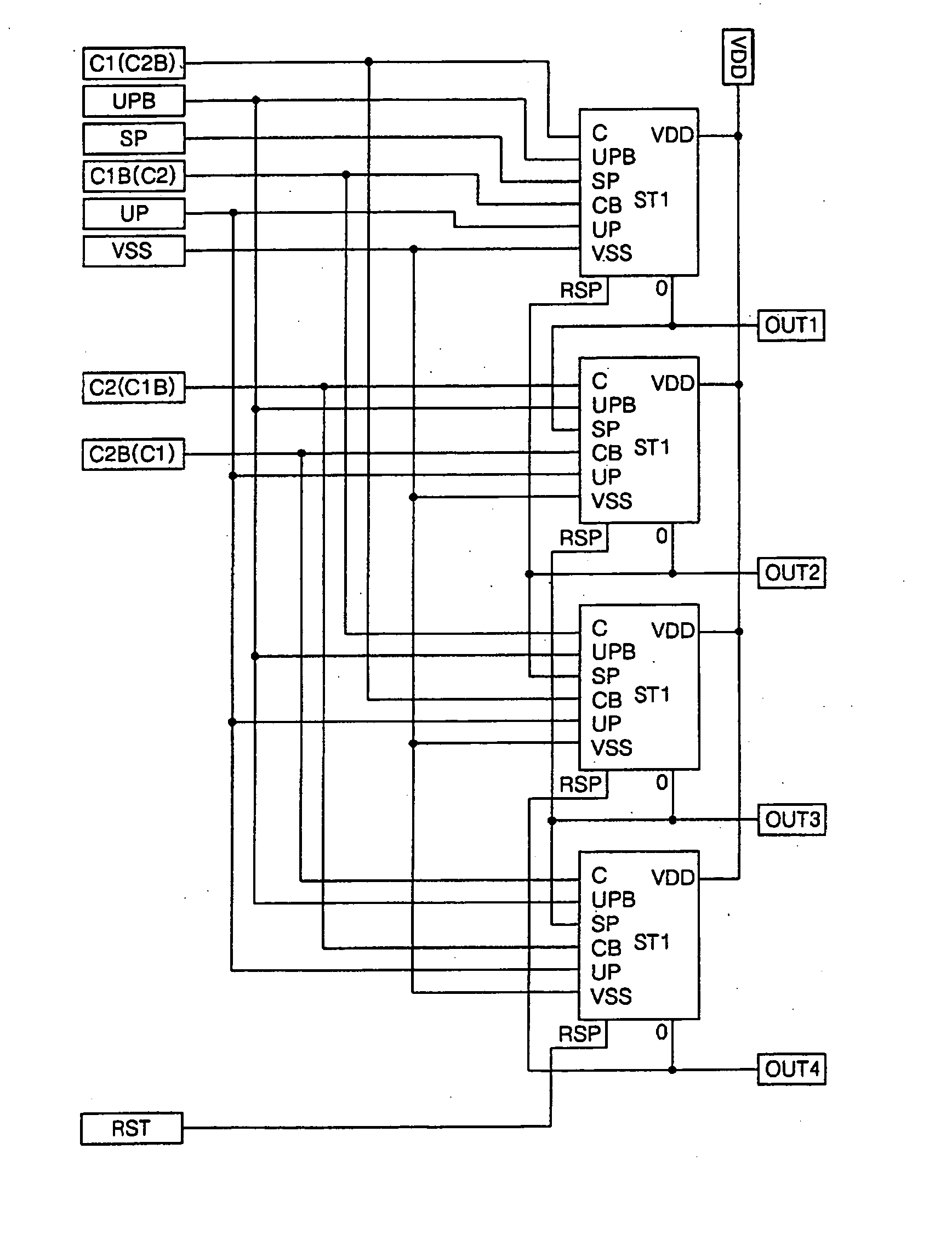
[0048]FIG. 3 is a detailed circuit diagram of one stage ST of a plurality of stages configuring a static shift register according to an exemplary embodiment of the present invention, and FIG. 4 is a driving waveform diagram of the stage ST shown in FIG. 3.

[0049] Each stage ST of the static shift register illustrated in FIG. 3 includes a charger 52 for charging a Q node in response to a clock signal C, a discharger 54 for discharging the G node in response to a forward start pulse SP or a backward start pulse RSP, a scan direction controller 56 for controlling a discharge path of the Q node according to direction control signals UP and UPB between the charger 52 and the discharger 54 to thereby control a scan direction, an inverter 58 for inverting a voltage at the Q node to output it as an output signal OUT, and a latch 60 fo...


PUM


Abstract

A shift register having a simple configuration and improved response and power consumption is disclosed. In the shift register, a plurality of stages are connected to each other in cascade and scanned in a bilateral direction. In the stages, a charger charges a first supply voltage into a first node in response to a clock signal. A discharger discharges the first node in response to a first start pulse or a second start pulse. A scan direction controller is connected between the charger and the discharger to discharge the first node into a different path in response to a scan direction control signal. An output part outputs any one of said first and second supply voltages as an output signal in response to a voltage at the first node. A latch part latches said output signal using said output signal and a clock signal inverted from said clock signal to feed back the latched output signal to the first node.

Description

[0001] This application claims the benefit of Korean Patent Application No. P2003-50892 filed in Korea on Jul. 24, 2003, which is hereby incorporated by reference for all purposes as if fully set forth herein. BACKGROUND OF THE INVENTION [0002] 1. Field of the Invention [0003] This invention relates to a shift register, and more particularly to a static shift register having a simple configuration as well as a bilateral characteristic. [0004] 1. Description of the Related Art [0005] Flat panel display devices, such as a liquid crystal displays (LCD), electro-luminescence (EL) display devices, and plasma display panels (PDP), etc. have replaced a cathode ray tube (CRT) in many applications. [0006] The LCD devices control the transmittance of light input from a light source using the dielectric anisotropy of the liquid crystal in accordance with an electric field, to display a picture. The EL display device, by contrast, emits light from a phosphorescent material using a re-combinatio...

Claims


Application Information

Patent Timeline
IPC IPC(8): G11C8/04G09G3/36G11C19/00G11C19/28
CPCG11C8/04G11C19/28G11C19/00G09G3/36
Inventor HAN, SANG-SOOLIM, KYOUNG-MOON
Owner LG DISPLAY CO LTD
Why Eureka
Try Eureka