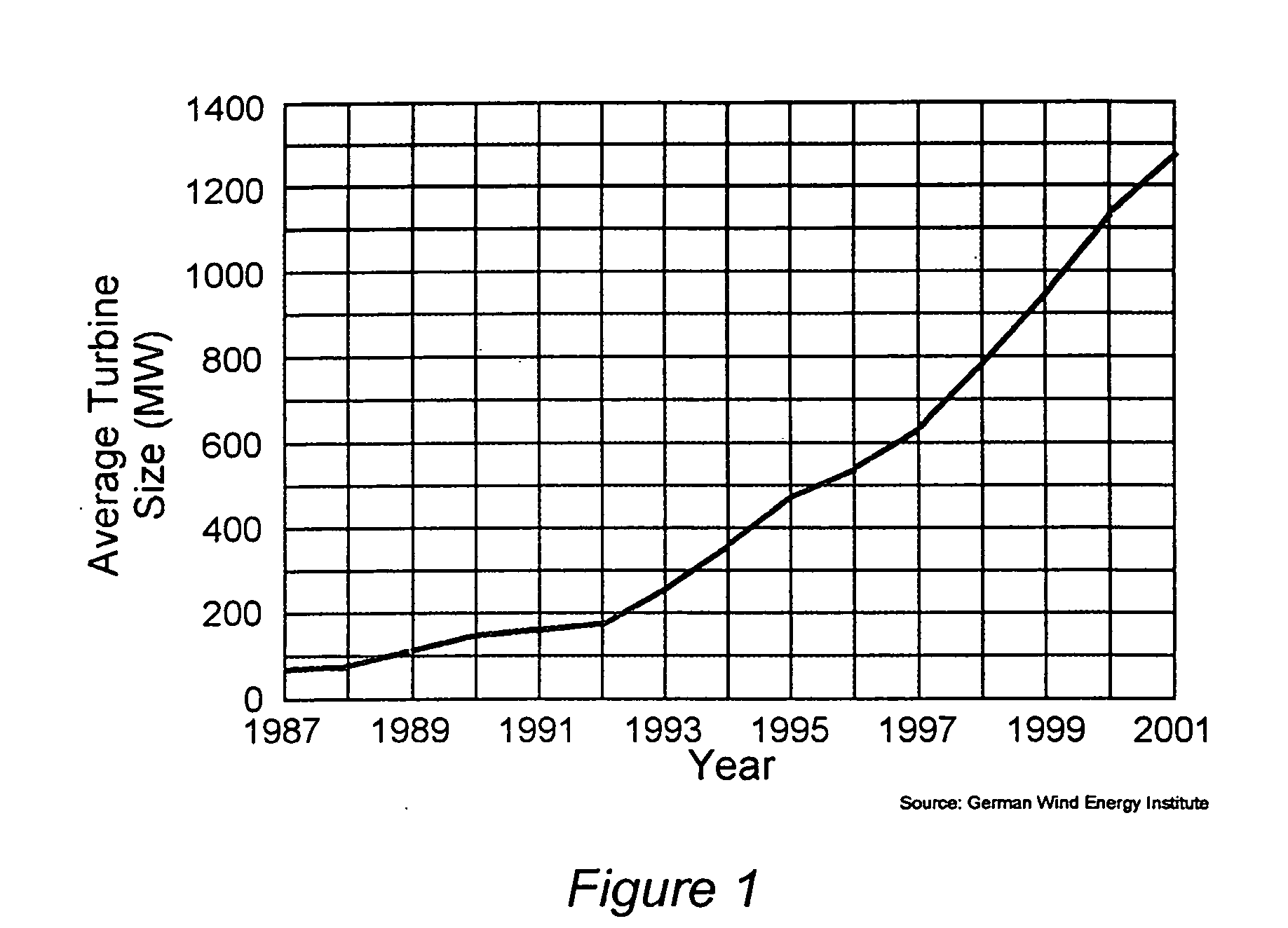
However, large turbines are also considerably more expensive than smaller machines and the economy of scale does not completely explain the trend to multi-megawatt size wind turbines.
Project developers have demanded larger wind turbines at least partly due to
perception issues.
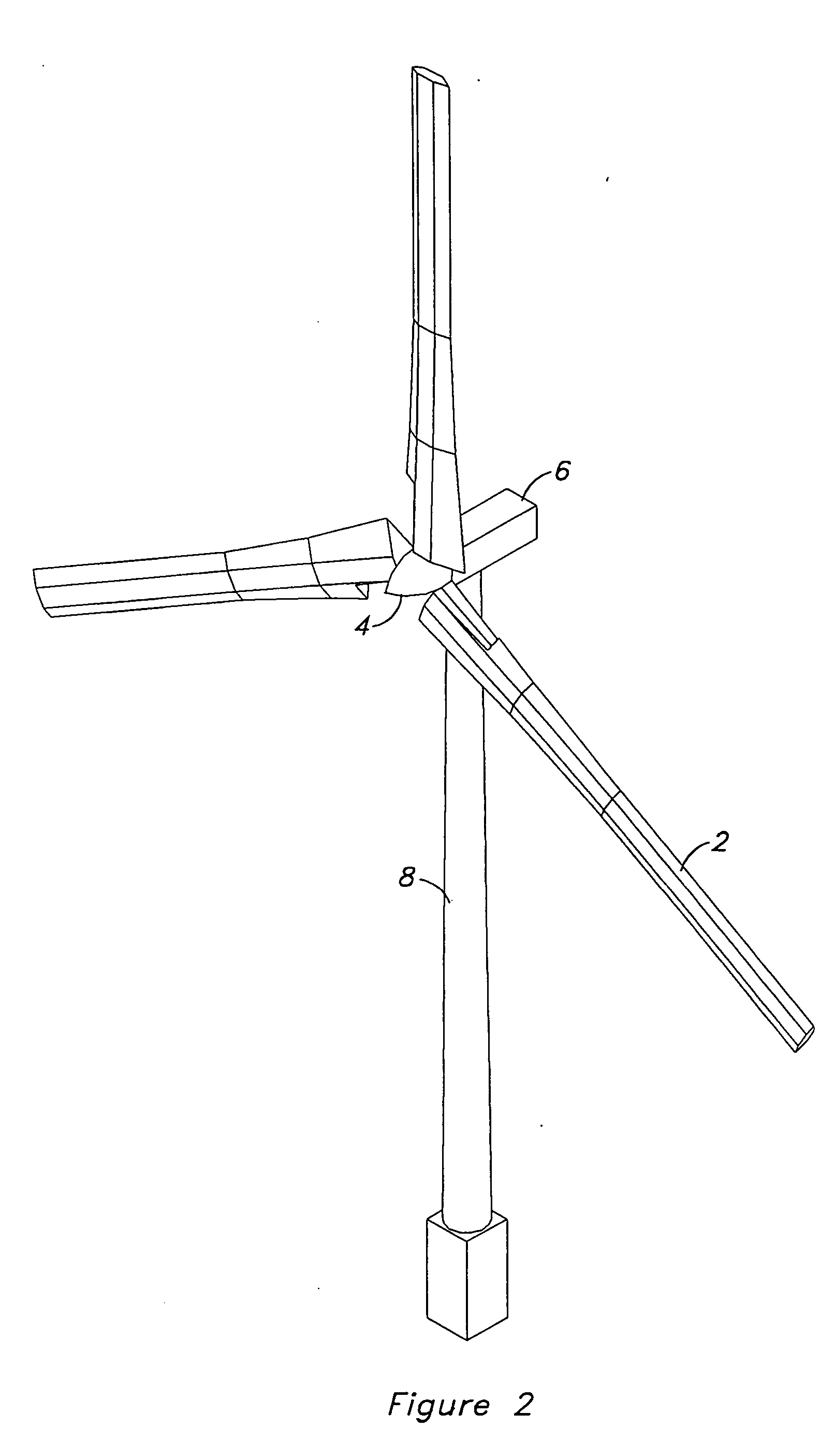
As the size of wind turbines grows, there are several technical issues that adversely affect the economics of wind energy and that can potentially lead to constraints in turbine size.
Another problem with large wind turbines is blade deflection.
However, the loads that cause deflection also increase for longer blades.
However, practical considerations such as tooling, blade weight, and material cost constrain the design so that the blade's chord and thickness are smaller relative to the blade's length for large rotors.
However,
noise issues tend to constrain
tip speed ratio so that centrifugal stiffening is less for very large rotors.
All of this points toward blade deflection becoming a limiting design criteria for very large wind turbine rotors.
Another issue with very large rotors is that there is a large amount of
composite material in each blade which can lead to material problems.
Statistically, there is a higher probability of a defect existing in a large blade than in a small blade.
If a defect is built into a blade, it can propogate to become a crack which will eventually lead to the blade's failure.
As the thickness of the blade's laminate increases, it becomes more and more difficult to detect flaws in the material.
Therefore, very large wind turbine blades may have a higher statistical
probability of failure than a larger number of smaller blades.
Another issue for very large wind turbines is transportation and installation logistics.
Also, the
tower heights necessary to support the large rotors can exceed the height capacity of cranes that are readily available.
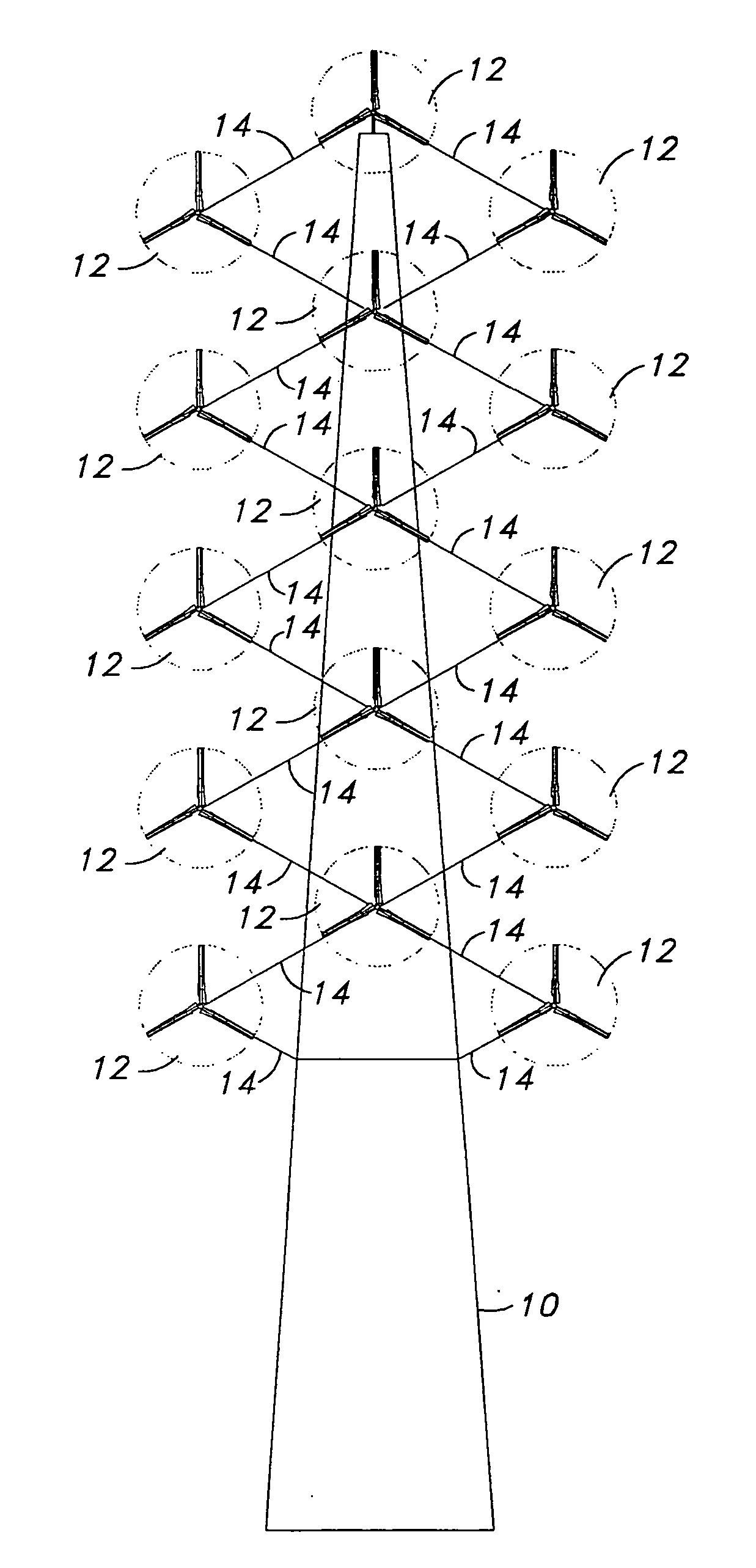
Another problem experienced by the large wind turbines that are currently under development or being sold is that the rotors are so large that they experience a massive differential in
wind speed from one side of the rotor to the other.
The variation in wind loading is even more severe since loads are generally proportional to
wind speed squared.
From an energy standpoint, things are even worse.
The
rotor speed and
blade pitch that work best for the wind speed at the rotor's center may not work well at all for the portions of the rotor at the top and bottom.
This problem is made worse as the turbine's rotor
diameter gets larger.
The issue of windspeed variation across the rotor also has negative implications for selecting an appropriate turbine for a given site.
When the wind turbine's rotor grows to be very large, it is more difficult to tailor the
power rating and rotor
diameter to fit the site.
Whichever rotor is selected, it will not be optimized for the entire rotor disk area.
As wind turbines grow very large there are several problems which need to be solved.
First, the weight and cost of the turbine grow disproportionately for a very large rotor diameter.
Second, blade deflection becomes a problem and limits the
rotor design for very large wind turbines.
Third, large wind turbine rotors have a greater statistical probability of material defects in the blades compared to smaller wind turbines.
Fourth, transportation and construction logistics are problematic for very large wind turbines.
Fifth, large wind turbines experience massive wind speed variations across their rotors so that at least a portion of the rotor is likely to be operating in sub-optimal conditions for the wind speed it is experiencing.
