Implantable duct system connecting the intrahepatic portal vein to the femoral vein for establishing a subcutaneous porto-systemic shunt and simultaneously providing a durable access to the portal vein

Inactive Publication Date: 2005-01-27
GABAL ABDELWAHAB M
View PDF5 Cites 14 Cited by
  • Summary
  • Abstract
  • Description
  • Claims
  • Application Information

AI Technical Summary

Benefits of technology

[0033] Diagram showing near coronal view of the duct (1) within the liver (19) with its inner opening (2) inside portal vein (20) while its hub (3) locates in the subcuta

Problems solved by technology

This leads to portal hypertension.
However, prolonged follow-up studies have revealed several complications and limitations.
The procedure is technically difficult and needs considerable experience to perform.
The path of the puncture set from the internal jugular vein to the hepatic vein traverses the right atrium of the heart, which increases risk of the procedure.
Frequent thrombosis of the stent resulting in occlusion of the shunt tract.
Difficult to be app

Method used


Image

  • Implantable duct system connecting the intrahepatic portal vein to the femoral vein for establishing a subcutaneous porto-systemic shunt and simultaneously providing a durable access to the portal vein
  • Implantable duct system connecting the intrahepatic portal vein to the femoral vein for establishing a subcutaneous porto-systemic shunt and simultaneously providing a durable access to the portal vein
  • Implantable duct system connecting the intrahepatic portal vein to the femoral vein for establishing a subcutaneous porto-systemic shunt and simultaneously providing a durable access to the portal vein

Examples


Embodiment Construction

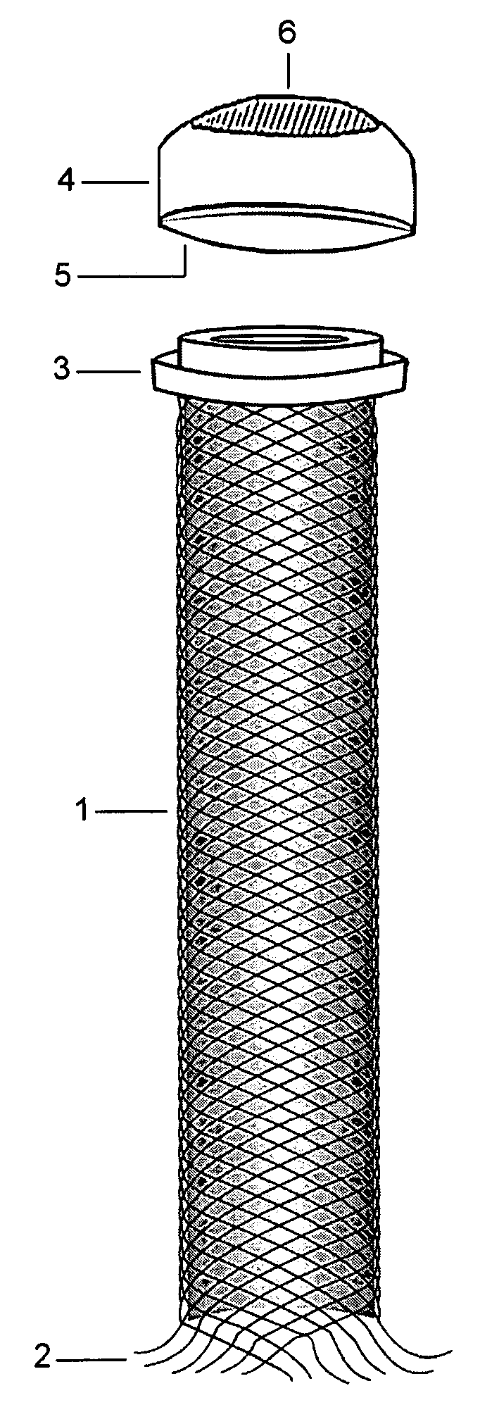
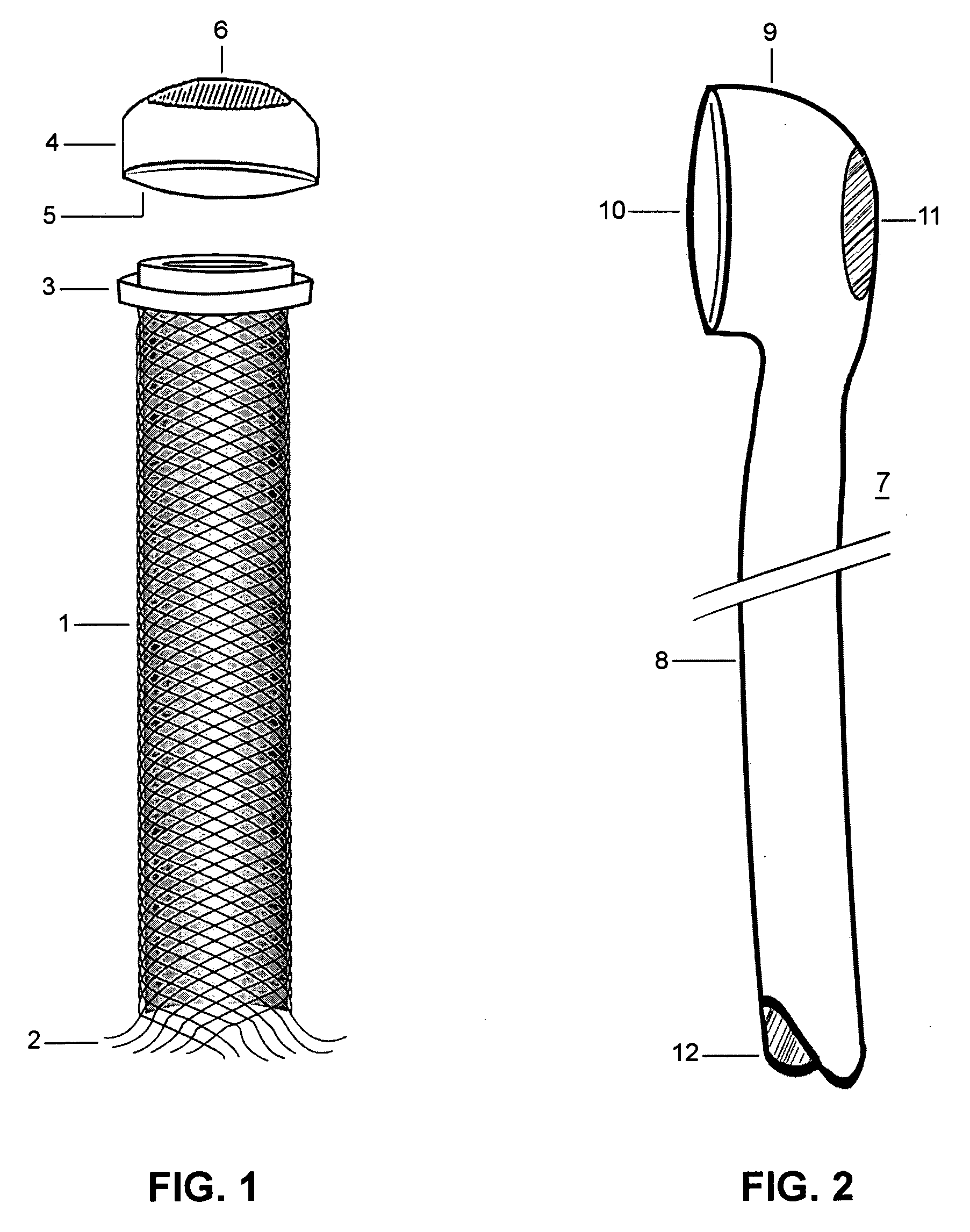
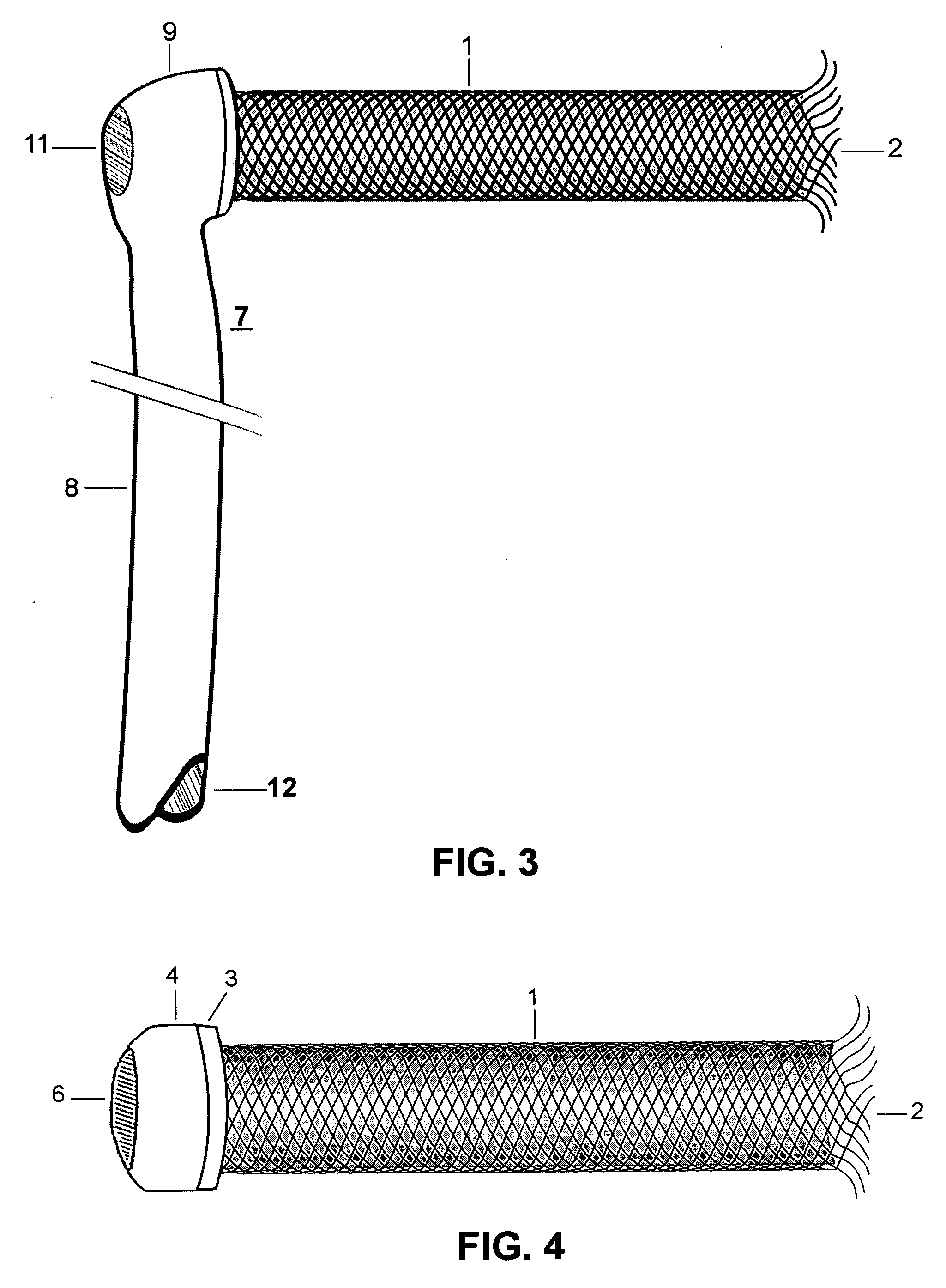
[0036] The system is composed of: a duct (1), and a shunt tube (7) when attached together they form continuous hollow channel (FIG. 3).

[0037] The said duct (1) is a tubular mesh constructed from highly flexible metal (Nitinol) and covered by a thin membrane of expanded Polytetrafluoroethylene (ePTFE). The said duct has two opened ends; the inner end (2) is formed by the edges of the said tubular mesh (1) which take a flaring form to provide internal fixation mechanism of the duct (1) within the portal vein (20). The outer end of the said duct is tightly soldered to a rounded hub (3). A cup-shaped plug (4) is provided to be applied to the hub (3) of the said duct (1) to prevent bleeding from the duct when it used as a durable port to the portal vein. The said plug (4) has a concave opened end (5) which matches the shape and diameter of the said hub (3). Back of the said plug has a window covered by a highly elastic membrane (6). It is designed to serve as a permeable entrance allowi...


PUM


Abstract

A set (FIG. 1&2) designed to provide a durable access to the portal vein and to divert portal blood to the systemic circulation in order to relieve congested portal system. The set is composed of a duct (1) and a shunt tube (7). The duct is composed of a covered flexible tubular braid with two opened ends. One end has flaring edges and forms the inner opening (2) while the other end is sealed to form a hub (3). To insert the duct into the intrahepatic portal vein through the percutaneous route the duct is mounted over a puncture needle (13) and contained in a small-constrained diameter by means of a peel-away sheath (16). After the position of the inner opening of the duct has been adjusted to the desired location the said sheath is peeled away to allow the duct to expand. The shunt tube (7) is composed of a long flexible vascular graft (8) equipped at its upper end with a head (9) while its lower end is free to be sutured with the femoral vein (21). The said head is cupped at the inner side (10) to fit in the hub (3) of the said duct (1), while back of the said head has a window covered with an elastic membrane (11). This shunt tube is applied in case both a portal access and a porto-systemic shunt are required. In case of only a durable portal access is needed, a plug (4) with a central window covered by an elastic membrane (6) is applied to the hub of the duct. This prevents bleeding from the duct and simultaneously allows entrance of needles, catheters, etc. to the duct and portal vein.

Description

BACKGROUND OF THE INVENTION [0001] Portal vein transfers portal blood from intestine and spleen to the liver where several chemical and biological processes take place before this blood passes into the general venous circulation through the hepatic veins. [0002] Diseases that affect liver parenchyma like liver cirrhosis and periportal fibrosis impede flow of portal blood through the liver. This leads to portal hypertension. Bleeding esophageal varices, ascites and encephalopathy are the end results of portal hypertension. [0003] For treatment of portal hypertension several surgical interventions have tried to decompress the portal system by establishing a shunt between portal vein or one of its branches and systemic venous circulation. The basic idea is to establish a communication or create a channel (shunt) between the portal and the systemic venous circulation, thus allowing the blood to be shunted from the high pressure within the portal venous system to the low pressure in the ...

Claims


Application Information

Patent Timeline
IPC IPC(8): A61B17/34A61F2/04A61F2/06A61M25/06
CPCA61B17/3423A61B2017/3419A61M25/0662A61F2002/061A61F2/04
Inventor GABAL, ABDELWAHAB M.
Owner GABAL ABDELWAHAB M
Why Eureka
Try Eureka