

Honeycomb structural body forming ferrule and method of manufacturing the ferrule
a technology of honeycomb and ferrule, which is applied in the direction of chemical coating, physical/chemical process catalyst, application, etc., can solve the problems of inability to meet the recent demands of extrusion-forming ceramic puddles, insufficient abrasion resistance of coating layers, and inability to obtain honeycomb structures that meet the recent demands. , to achieve the effect of improving the productivity of honeycomb structures, avoiding poor forming, and improving the efficiency of extrusion-forming
- Summary
- Abstract
- Description
- Claims
- Application Information
AI Technical Summary
Benefits of technology
Problems solved by technology
Method used
Image

Examples
example 1
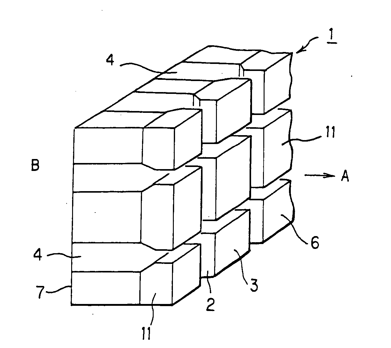
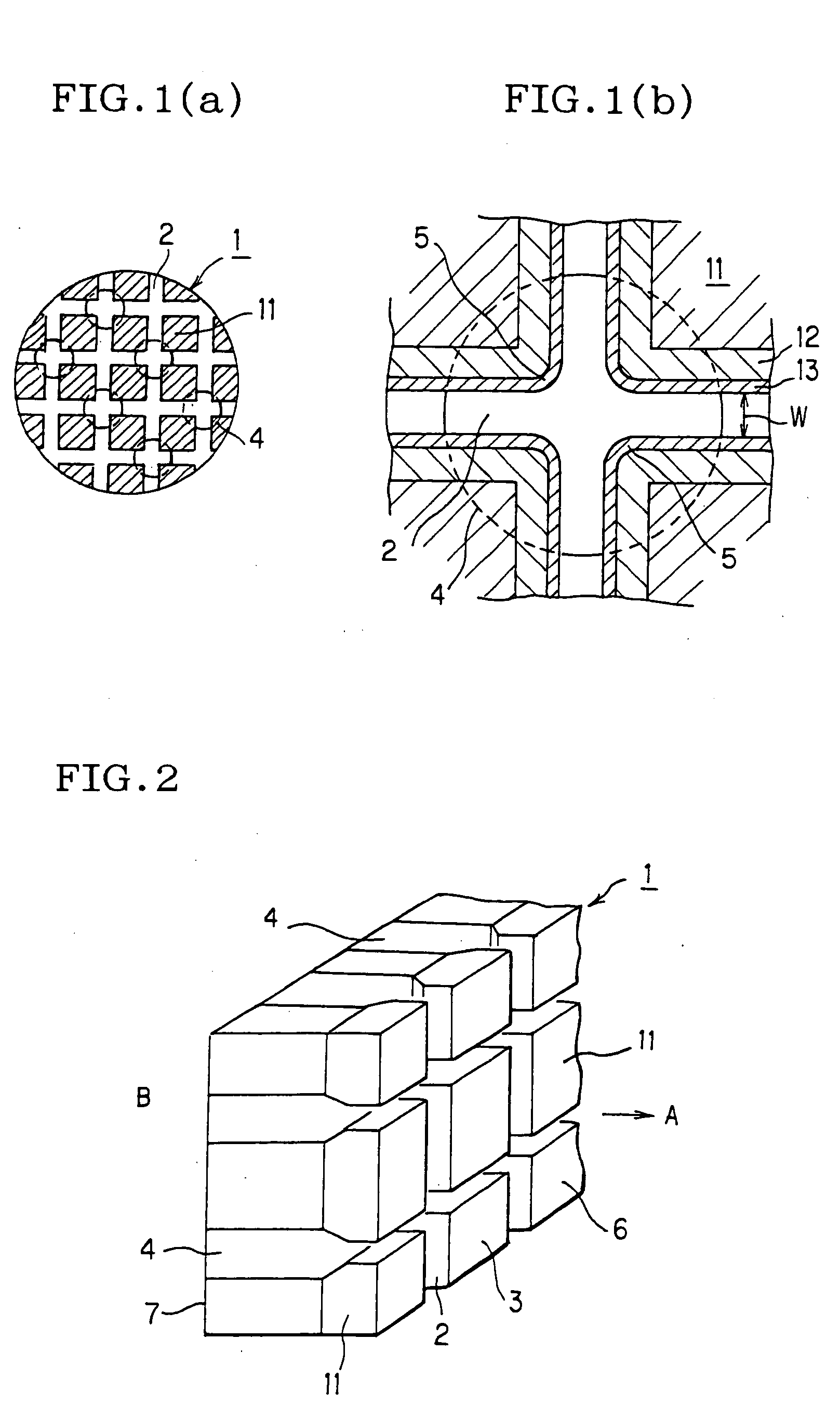
First, a plate material consisting of SUS was machined on a lathe and a grinding wheel to be a square plate 250 mm×250 mm×20 mm (length×breadth×thickness). Then, slits 180 μm wide and 3.0 mm deep were cut at 1.0 mm intervals in one end face of the square plate by EDM and grinding. And another slits were cut in the same manner as above so that they were at right angles to the above cut slits. In the meantime, ceramic puddle introducing holes 1.00 mm in diameter and 18 mm deep were made at 1.0 mm intervals in the other end face of the square plate by ECM in such a manner as to position their central axes at the intersections (every other intersection) of the above cut slits so that they were in communication with the slits.
Then, the square plate thus obtained was machined into a disk 200 mm in outside diameter by EDM, degreased, and immersed in a 35% hydrochloric acid bath for one minute to be pre-treated. After that, the disk was plated in a nickel phosphate bath at one continuous...
example 3
First, a plate material consisting of SUS was machined on a lathe and a grinding wheel to be a square plate 250 mm×250 mm×20 mm (length×breadth×thickness). Then, slits 180 μm wide and 3.0 mm deep were cut at 1.5 mm intervals in one end face of the square plate by EDM and grinding. And another slits were cut in the same manner as above so that they were at right angles to the above cut slits. In the meantime, ceramic puddle introducing holes 1.40 mm in diameter and 18 mm deep were made at 1.5 mm intervals in the other end face of the square plate by ECM in such a manner as to position their central axes at the intersections (every other intersection) of the above cut slits so that they were in communication with the slits.
Then, the square plate thus obtained was machined into a disk 200 mm in outside diameter by EDM, degreased, and immersed in a 35% hydrochloric acid bath for one minute to be pre-treated. After that, the disk was plated in a nickel phosphate bath at one continuous...
PUM
| Property | Measurement | Unit |
|---|---|---|
| width | aaaaa | aaaaa |
| particle diameter | aaaaa | aaaaa |
| thick | aaaaa | aaaaa |
Abstract
Description
Claims
Application Information