Apparatuses and methods for heart valve repair

a heart valve and appendix technology, applied in the field of appendixes and methods for heart valve repair, can solve the problems of ineffective closing of leaflets of the valve(s), affecting the operation of the valve, and the annular enlargement can become so large, so as to reduce the distance between the distal anchoring member and the annular siz

Inactive Publication Date: 2005-02-17
ABBOTT CARDIOVASCULAR
View PDF99 Cites 162 Cited by
  • Summary
  • Abstract
  • Description
  • Claims
  • Application Information

AI Technical Summary

Benefits of technology

[0014] In one exemplary embodiment of the present invention, a medical device for treating mitral valve is disclosed. The medical device comprises a distal anchoring member for disposing in a blood vessel and a proximal anchoring member for disposing in or at an entrance of the blood vessel, and a telescoping assembly coupling at a first end to the distal anchoring member and at a second end to the proximal anchoring member. The telescoping assembly is deployable into the blood vessel. The telescoping assembly reduces a distance between the distal anchoring member and the proximal anchoring member, wherein the telescoping assembly comprises at least two members capable of sliding into or along each other giving the telescoping assembly adjustable lengths. The distal anchoring member and the proximal anchoring member anchor or attach to the inner wall of the blood vessel or a cardiac tissue allowing the telescoping assembly to draw them toward each other. Reducing the distance between the distal anchoring member and the proximal anchoring member allows the medical device to reshape the mitral valve or the mitral valve annulus.

Problems solved by technology

A normal mitral valve allows blood to flow into the left ventricle and does not allow leaking or regurgitating back into the left atrium and then into the lungs during systole.
The aortic valve allows blood to flow into the aorta and does not allow leaking (or regurgitating) back into the left ventricle.
This enlargement can cause the annular size of the valves that separate the atria from the ventricles to also become enlarged.
The annular enlargements can become so pronounced that the leaflets of the valve(s) are unable to effectively close.
This reduction in blood flow can be life threatening, especially in patients that have lost ventricular tissue (i.e. heart attack victims), have contraction synchronization problems and / or other problems that reduce the heart's ability to act as a pump.
While surgical procedures such as those mentioned can successfully reconstruct the valve back to a non-regurgitant state, this problem is often associated with Chronic Heart Failure (CHF) and / or other debilitating diseases and thus, the sufferers of the regurgitant valve are often unable to tolerate the required open heart surgery.
In CHF patients, the heart is progressively less able to pump sufficient blood to meet the body's needs, usually due to the continuing enlargement of the left ventricle (and adjacent structures) in response to high blood pressure, high heart rate, ECG conduction / timing problems and / or insults to the ventricular tissue, such as Myocardial Infarct (MI).
As the body's cardiac compensatory mechanisms act to maintain blood flow (cardiac output), the increased stress and metabolic impacts cause further cardiac enlargement and other detrimental changes.
The onset of mitral valve regurgitation further reduces cardiac output and, thus accelerates the CHF process.

Method used


Image

  • Apparatuses and methods for heart valve repair
  • Apparatuses and methods for heart valve repair
  • Apparatuses and methods for heart valve repair

Examples


Embodiment Construction

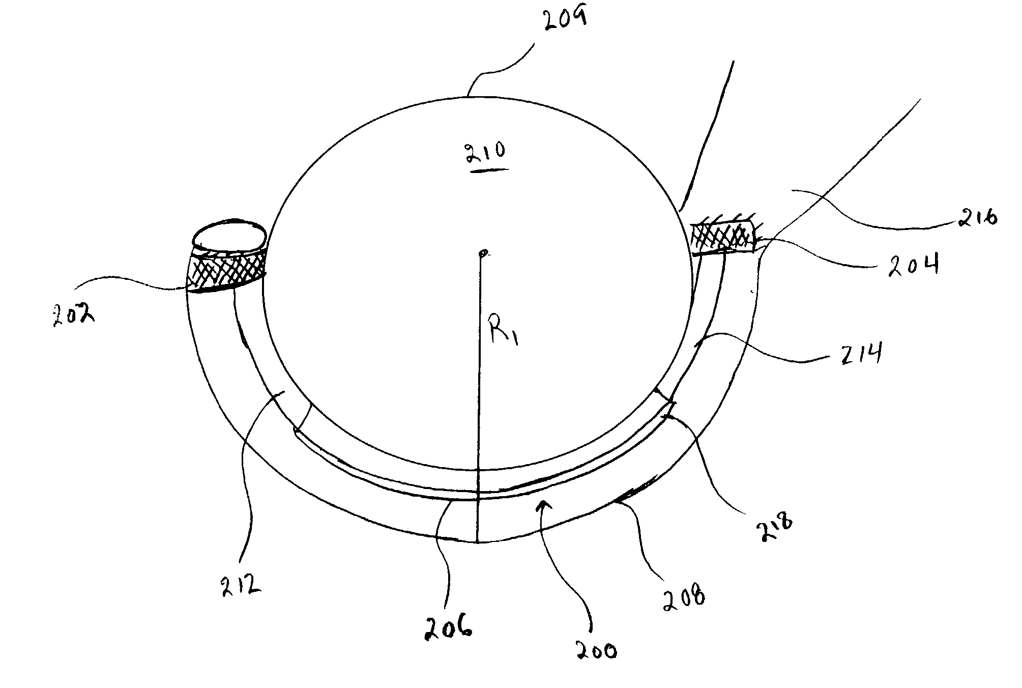
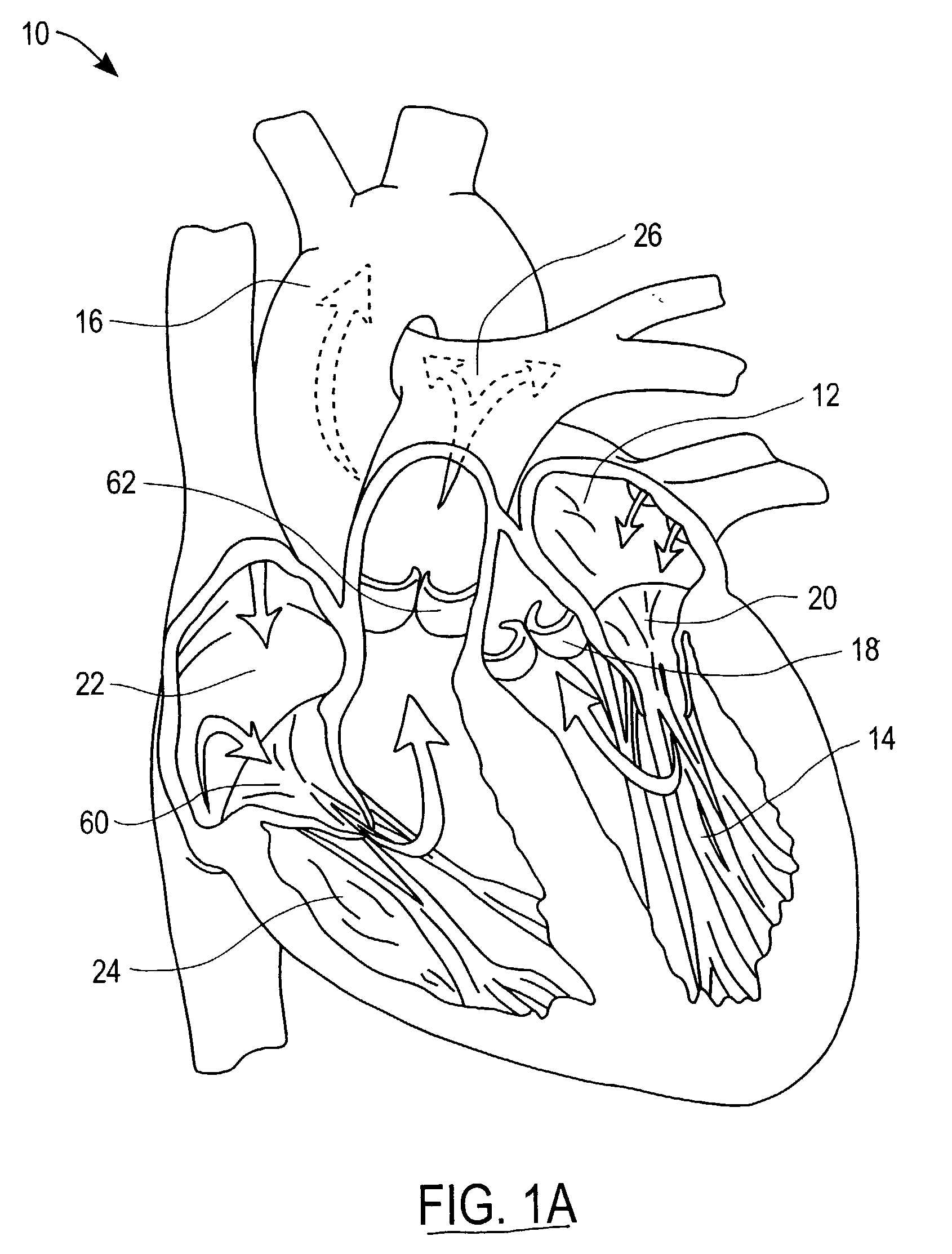
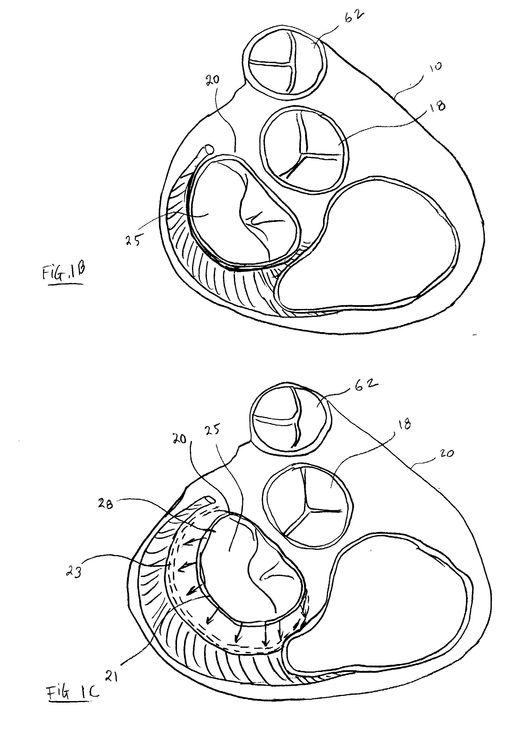
[0056] The exemplary embodiments of the present invention pertain to novel annuloplasty devices, delivery devices to deploy / deliver the annuloplasty devices, and methods of using these annuloplasty devices to treat medical conditions such as defective or faulty heart valves. In the following description, for purposes of explanation, numerous specific details are set forth in order to provide a thorough understanding of the present invention. It will be evident, however, to one skilled in the art, that the present invention may be practiced without these specific details. In other instances, specific apparatus structures and methods have not been described so as not to obscure the present invention. The following description and drawings are illustrative of the invention and are not to be construed as limiting the invention.

[0057] In some exemplary embodiments of the present invention, an annuloplasty device used for treating a faulty heart valve such as those seen in MVR includes a...


PUM


Abstract

A medical device for treating a defective heart valve. The medical device comprises a distal anchoring member for disposing in a blood vessel. A proximal anchoring member for disposing in or at an entrance of the blood vessel. A telescoping assembly coupling at a first end to the distal anchoring member and at a second end to the proximal anchoring member. The telescoping assembly is deployable into the blood vessel. The telescoping assembly reduces a distance between the distal anchoring member and the proximal anchoring member, wherein the telescoping assembly comprises of at least two members capable of sliding into each other giving the telescoping assembly adjustable lengths.

Description

BACKGROUND OF THE INVENTION [0001] 1. Field of the Invention [0002] The present invention involves annuloplasty devices and delivery devices for the annuloplasty devices that are used for treating a medical condition such as a defective mitral valve. [0003] 2. Discussion of Related Art [0004]FIG. 1A illustrates a heart 10. There are four valves in the heart 10 that serve to direct the flow of blood through the two sides of the heart 10 in a forward direction. The four valves are a mitral valve 20, an aortic valve 18, a tricuspid valve 60, and a pulmonary valve 62 as illustrated in FIG. 1A. The mitral valve 20 is located between the left atrium 12 and the left ventricle 14. The aortic valve 18 is located between the left ventricle 14 and the aorta 16. These two valves direct oxygenated blood coming from the lungs, through the left side of the heart, into the aorta 16 for distribution to the body. The tricuspid valve 60 is located between the right atrium 22 and the right ventricle 24...

Claims


Application Information

Patent Timeline
Patent Type & Authority Applications(United States)
IPC IPC(8): A61F2/02A61F2/24A61F2/82
CPCA61F2/2451A61F2/91Y10T24/39A61F2250/001A61F2002/828
Inventor WEBLER, WILLIAM E.HYDE, GREGORY MATHEWFEEZOR, CHRISTOPHERCOX, DANIEL L.
Owner ABBOTT CARDIOVASCULAR
Why Eureka
Try Eureka