High-temperature protection layer

a protection layer and high-temperature technology, applied in the field of high-temperature protection layers, can solve the problems of thermally activated phase transitions, microstructures with undesirable phases, and disadvantageously high volume proportions of - and/or -nial

a protection layer and high-temperature technology, applied in the field of high-temperature protection layers, can solve the problems of thermally activated phase transitions, microstructures with undesirable phases, and disadvantageously high volume proportions of - and/or -nial

US20050042474A1Inactive Publication Date: 2005-02-24ANSALDO ENERGIA IP UK LTD

Image

  • High-temperature protection layer
  • High-temperature protection layer

Examples


Embodiment Construction

[0023] The invention is explained in more detail on the basis of an exemplary embodiment, which describes the production of a coated gas turbine component or another component of a thermal turbomachine. The gas turbine component to be coated is made from an austenitic material, in particular a nickel superalloy. Before it is coated, the component is first chemically cleaned and then roughened using a blasting process. The component is coated under a vacuum, under shielding gas or in air by means of thermal spraying processes (LPPS, VPS, APS), high-velocity spraying (HVOF), electrochemical processes, physical / chemical vapor deposition (PVD, CVD) or another coating process which is known from the prior art.

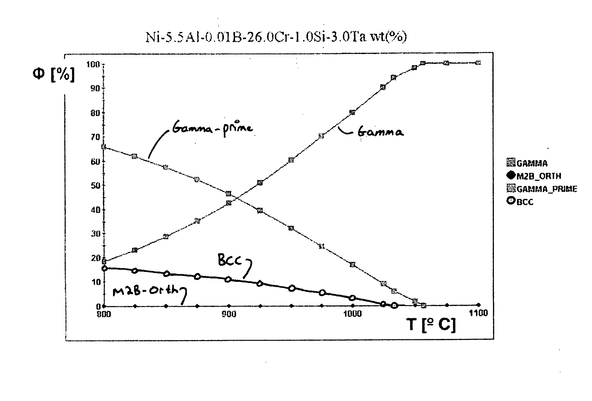
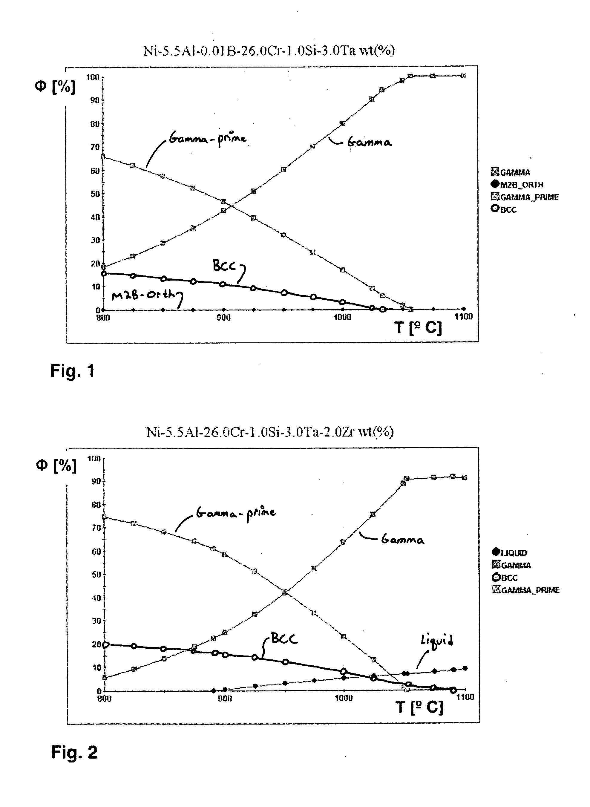
[0024] An NiCrAlY alloy which, according to the invention, includes (% by weight) 23 to 27% by weight of chromium, 4 to 7% by weight of aluminum, 0.1 to 3% by weight of silicon, 0.1 to 3% weight of tantalum, 0.2 to 2% by weight of yttrium, 0.001 to 0.01% by weight of boron, 0.001 t...


PUM

PropertyMeasurementUnit
Temperatureaaaaaaaaaa

Abstract

A high-temperature protection layer contains (% by weight) 23 to 27% Cr, 4 to 7% Al, 0.1 to 3% Si, 0.1 to 3% Ta, 0.2 to 2% Y, 0.001 to 0.01% B, 0.001 to 0.01% Mg and 0.001 to 0.01% Ca, remainder Ni and inevitable impurities. Optionally, the Al content is in a range from over 5 up to 6% by weight.

Description

[0001] This application is a Continuation of, and claims priority under 35 U.S.C. § 120 to, International application number PCT / CH03 / 00023, filed 16 Jan. 2003, and claims priority under 35 U.S.C. § 119 to German application number 102 02 012.4, filed 18 Jan. 2002, the entireties of both of which are incorporated by reference herein.BACKGROUND OF THE INVENTION [0002] 1. Field of the Invention [0003] The invention relates to a high-temperature protection layer. [0004] 2. Brief Description of the Related Art [0005] High-temperature protection layers of this type are used in particular where the base material of components made from heat-resistant steels and / or alloys used at temperatures over 600° C. is to be protected. [0006] These high-temperature protection layers are intended to slow down or completely suppress the action of high-temperature corrosion, in particular caused by sulfur, oil ashes, oxygen, alkaline-earth metals and vanadium. High-temperature protection layers of this ...

Claims


Application Information

Patent Timeline
24 Feb 2005
Publication
US20050042474A1
IPC
C22C19/05; F01D5/18; C23C4/073; C23C4/08; C23C26/00; C23C28/00; C23C30/00; F01D5/28; F01D9/02; F02C7/00; F23R3/42
CPC
C23C4/085; C23C30/00; Y10T428/26; Y10T428/12944; Y10T428/12611; Y10T428/12937; C23C4/073
Inventors
BOSSMANN, HANS-PETER; ECKARDT, DIETRICH